Door mounting frame COG11A

Proceed as follows:
- Fasten the drilling template to the mounting surface [1].
- Center punch the 5 mm bores [4] for the screws [3] and the 40 mm bore [2] for the D‑sub connector using the drilling template.
- Remove the drilling template.
- Drill the bores.
- Clean the mounting surface [1].
- Place the door mounting frame [5] from outside onto the mounting surface [1].
- Fix the door mounting frame in place using the screws [3] supplied (max. 2.5 Nm).
- If you are using a UKS52A cable, insert the port saver from behind through the 40 mm bore [2] and tighten the screws evenly.
- Insert the D-sub connection cable from behind through the 40 mm bore [2] and tighten the screws evenly.
- Connect the connection cable to the inverter and tighten the screws evenly.
- Open the cover.
- Insert the keypad and perform a functional check.
- Close the cover and tighten the cover screw (1.2 – 1.4 Nm).
The following figure shows the installed door frame with CBG21A using the example of MOVITRAC® classic.
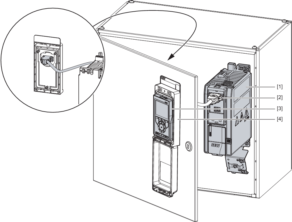
[1] | MOVITRAC® classic inverter |
[2] | D-Sub cable, 9-pin |
[3] | CBG21A keypad |
[4] | COG11A door mounting frame |
Technical data COG11A | |
|---|---|
Compatible devices |
|
Part number | 28265688 |
Scope of delivery |
|
Connection | Connector D-sub, 9‑pin, female |
Protection class | IP65 with tightening torque of 1.2 to 1.4 Nm for the cover screw Enclosure UL Type I |
Dimensions (H × W × D) |
|
Maximum metal thickness of the control cabinet door | 7 mm |
Space required for cover | 200 mm |
