Sizes X100 – 160
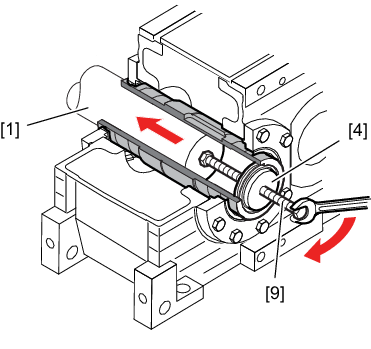
- Loosen the locking screws [10] by a quarter turn one after the other to avoid straining the connecting surface.
INFORMATION

If the outer ring (stepped tapered ring) [9a] and the inner ring (stepped tapered bushing) [9b] do not loosen by themselves: Take the necessary number of screws and screw them evenly into the disassembly bores. Tighten the locking screws in several steps until the tapered bushing separates from the tapered ring.
- Remove the shrink disk from the hollow shaft.
- Loosen the retaining screw [6]. Remove the outer retaining ring [8] and pull off the end plate [4].
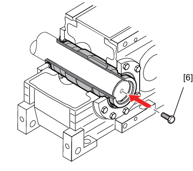
- To protect the centering bore, screw the retaining screw [6] into the machine shaft [1].
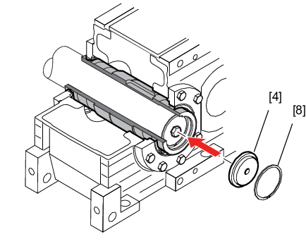
- Turn the end plate [4] and reinstall the end plate [4] and the outer retaining ring [8].
- Thread the ejector screw [8] into the end plate [4] to remove the gear unit from the machine shaft [1]. Disassembly is easier if you first apply lubricant to the ejector screw [8] and the thread in the end plate [4].
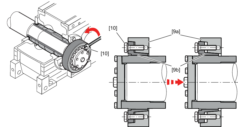
[9a] | Outer ring (stepped tapered ring) |
[9b] | Taper bushing (inner ring) |
[10] | Locking screws |
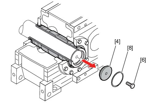
[4] | End plate |
[6] | Retaining screws |
[8] | Retaining ring |
[1] | Machine shaft |
[6] | Retaining screws |
[4] | End plate |
[8] | Retaining ring |
[1] | Machine shaft |
[4] | End plate |
[8] | Retaining ring |
- Thoroughly clean the removed shrink disk from dirt and the remaining adhering lubricants.
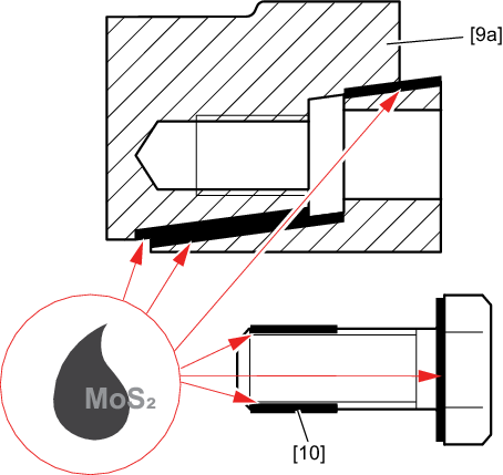
- Apply an MoS2 compound onto the threads and under the screw heads of the locking screws [10], for example "gleitmo 100" from FUCHS LUBRITECH (www.fuchs-lubritech.com).
- Apply a thin layer of an MoS2 compound onto the tapered surface, as shown in the following figure, for example "gleitmo 100" from FUCHS LUBRITECH (www.fuchs-lubritech.com).
INFORMATION
