Size X170 – 320
INFORMATION

- Included in the scope of delivery:
- Retaining screws [3] and end plate [4].
- Not included in the scope of delivery:
- Threaded rod [2], nut [5], retaining screw [6], ejector screw [8].
- Before mounting the gear unit, degrease the hollow shaft [7] and the machine shaft [1]. Use a commercially available solvent. Do not let the solvent come into contact with the sealing lips of the oil seals.
- It is essential that the clamping area of the shrink disk between the machine shaft [1] and the hollow shaft [7] remains free of grease.
- Apply some assembly paste, such as NOCO-Paste to the machine shaft [1] in the area of the bushing [11].
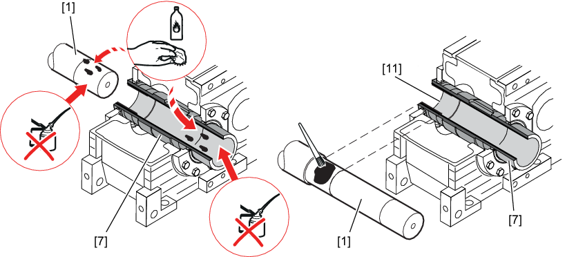
[1] | Machine shaft | [11] | Socket |
[7] | Hollow shaft |
|
|
- Use the retaining screws [3] to attach the end plate [4] centrically to the hollow shaft [7]. Thread the threaded rod [2] into the machine shaft [1].
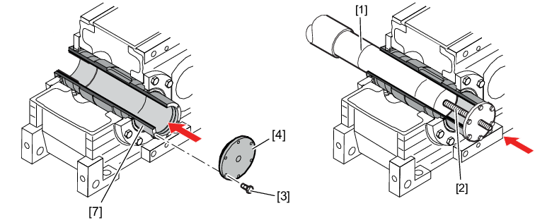
[1] | Machine shaft | [4] | End plate |
[2] | Threaded rod | [7] | Hollow shaft |
[3] | Retaining screws |
Observe the following thread sizes of the threaded rods [2].
|
Size |
Strength class 8.8 |
|---|---|
|
X..H170 – 230 |
M30 |
|
X..H240 – 300 |
M36 |
|
X..H310 – 320 |
M42 |
Observe the following information on the retaining screws [3].
Size | Thread size for | Tightening torque | |
|---|---|---|---|
Assembly/operating state | Disassembly | ||
X..H170 – 190 | M10 x 30 | 78 | Tighten hand-tight |
X..H200 – 230 | M12x30 | 135 | Tighten hand-tight |
X..H240 – 300 | M16x40 | 330 | Tighten hand-tight |
X..H310 – 320 | M20x50 | 645 | Tighten hand-tight |
- Screw the nut [5] onto the threaded rod up to the end plate [4]. Tighten the nut [5] until the shaft shoulders of the machine shaft [1] and the hollow shaft meet.
- Loosen the nut [5]. Remove the threaded rod [2].
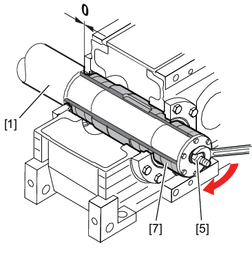
[1] | Machine shaft | [7] | Hollow shaft |
[5] | Nut |
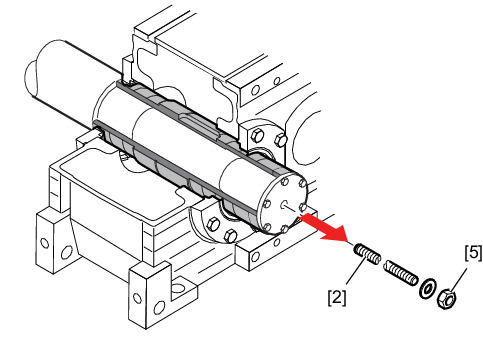
[2] | Threaded rod | [5] | Nut |
- Secure the machine shaft [1] with the retaining screw [6]. The retaining screw is also to be locked with a suitable threadlocker. Observe the following information on the retaining screw [6].
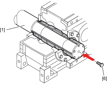
[1] | Machine shaft | [6] | Retaining screw |
Size | Strength class 8.8 | Tightening torque in Nm |
|---|---|---|
X..H170 – 230 | M30 | 1590 |
X..H240 – 300 | M36 | 2760 |
X..H310 – 320 | M42 | 4410 |
- Slide the shrink disk [9] with untightened screws onto the hollow shaft [7] and position the inner ring of the shrink disk [9b] at dimension A.
- Secure the shrink disk against slipping.
- Never tighten the locking screws without the shaft installed.
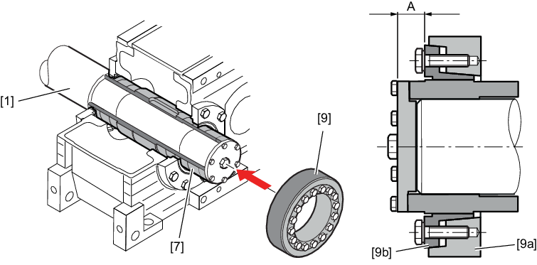
[7] | Hollow shaft | [9a] | Outer ring (stepped tapered ring) |
[9] | Shrink disk | [9b] | Inner ring (stepped tapered bushing) |
Size | A ±0.5 in mm |
|---|---|
XH170 – 190 | 37 |
XH200 – 210 | 38 |
XH220 – 230 | 39 |
XH240 – 260 | 48 |
XH270 – 300 | 49 |
XH310 – 320 | 60 |
- Tighten the locking screws [10] hand-tight. In doing so, align the outer ring (stepped tapered ring) [9a] parallel to the inner ring (stepped tapered bushing) [9b] of the shrink disk. Tighten the locking screws [10] one after the other in a clockwise direction (not in diametrically opposite sequence), each by a quarter turn. Do not tighten the locking screws [10] in a diametrically opposite sequence.
- Work around the ring in several stages, evenly tighten the locking screws [10] by a quarter turn until the outer ring (stepped tapered ring) [9a] and the inner ring (stepped tapered bushing) [9b] align on the face that holds the screws.
INFORMATION
For shrink disks with a slotted inner ring (stepped tapered bushing) [9b], tighten the locking screws [10] to the left and right of the slot one after another, and then, in several stages, tighten the remaining screws at evenly spaced intervals.
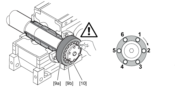
[9a] | Outer ring (stepped tapered ring) | [10] | Locking screws |
[9b] | Inner ring (stepped tapered bushing) |
|
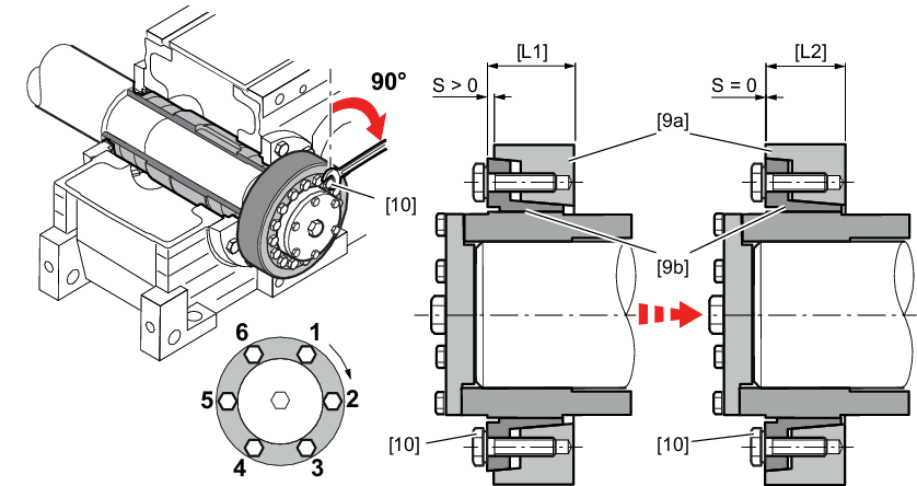
[9a] | Outer ring (stepped tapered ring) | [L1] | Condition at the time of shipment (pre-assembled) |
[9b] | Inner ring (stepped tapered bushing) | [L2] | Completely assembled (ready for operation) |
[10] | Locking screws |
|
|
|
|
|
|
|
|
|
|
If the outer ring (stepped tapered ring) and the inner ring (stepped tapered bushing) cannot be installed in alignment on the screw-side face, check the following tolerances for dimension S. These must not be exceeded while adhering to the maximum tightening torques (e.g. using a torque wrench) of the clamping screws [10].
Dimension S:
Outer diameter of the shrink disk | Dimension S |
|---|---|
≤Ø 100 | +0.1 |
≤Ø 300 | +0.2 |
above | +0.25 |
Maximum tightening torques of the clamping screws [10]:
Clamping screws [10] | Maximum tightening torque in Nm |
|---|---|
M10 | 62 |
M12 | 108 |
M14 | 171 |
M16 | 262 |
M18 | 367 |
M20 | 513 |
M22 | 696 |
M24 | 882 |
M27 | 1287 |
M30 | 1755 |
If the tolerance values are not adhered to, remove the shrink disk again and clean/lubricate it carefully according to the following chapter.
- Mount the protection cover dust-tight to the gear unit.
