Encoder connection
When connecting the encoders to the inverters, follow the operating instructions for the inverter and the wiring diagrams supplied with the encoders.
There may be differing requirements or limitations for the EI7C FS safety encoder due to the encoder evaluation unit, e.g. regarding the maximum cable lengths or the core cross sections. Observe the product documentation for the encoder evaluation unit for this.
Mechanical requirements
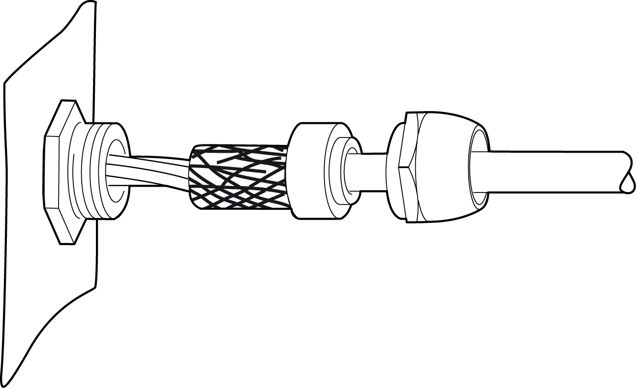
- For connection variants with M12 or M23 connector, a strain relief of the cable must be carried out by the customer in accordance with IEC 60079‑14.
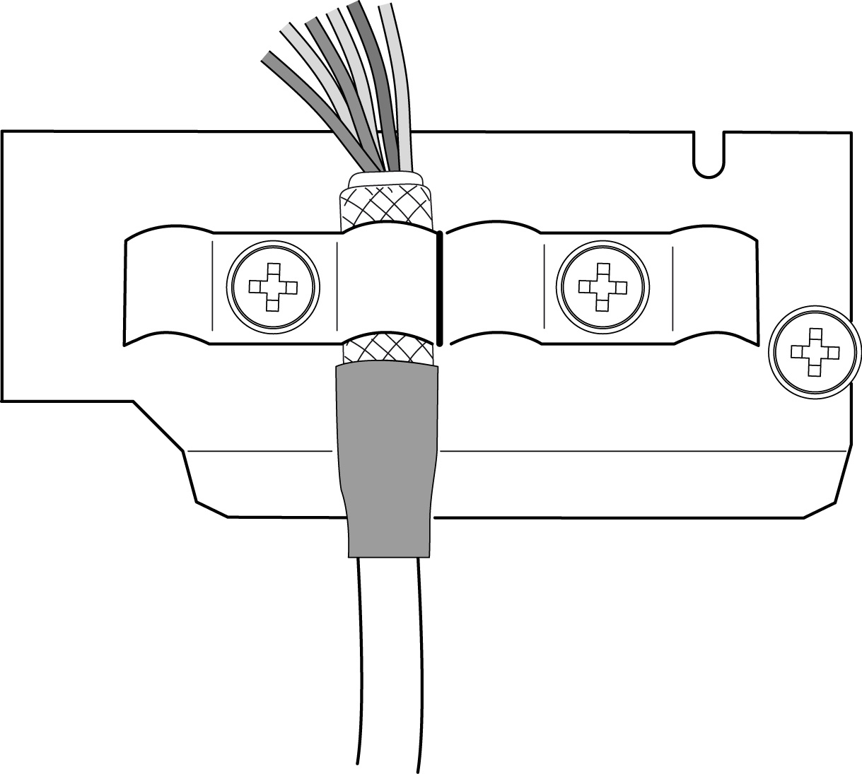
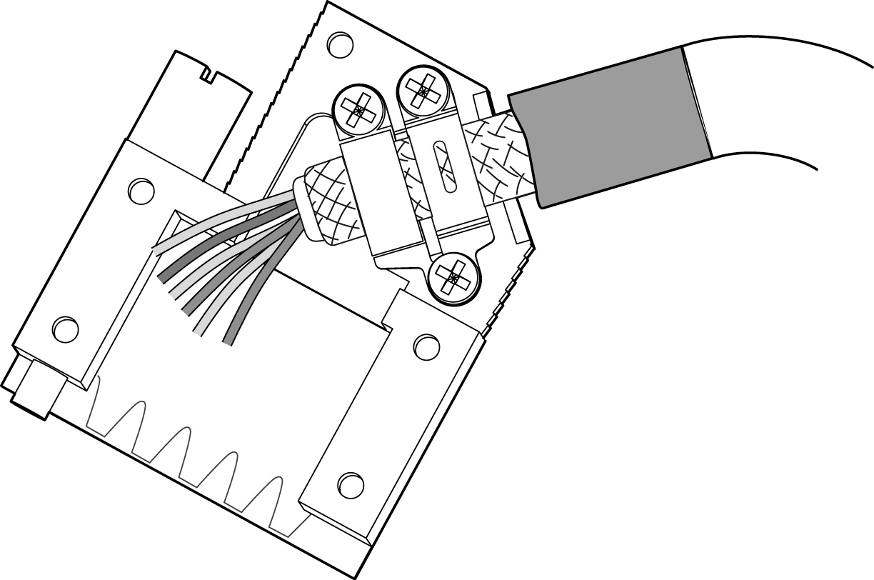
- Note the following for connection variants with terminal strips or connection units:
- Cables and cores must be mechanically protected against damage when they come into contact with motor components in the terminal box. Use fabric hoses.
- Cables and cores must be electrically shielded from live parts such as terminal boards or power terminals of the motor. Observe the required air gaps and creepage distances.
- Observe possible requirements regarding conformity with UL or CSA. For mechanical and electrical protection, use suitable glass fiber sheathing with UL style, for example.
Electrical requirements
- Polarity protection and overvoltage protection
- Signal cables
Short-circuit protection: | |
Signal outputs against each other | ✔ |
Against supply | – |
Against GND | ✔ |
Against encoder housing | ✔ |
Against shielding | ✔ (Assumption: Potential difference of GND to shielding: 0 V) |
Minimum short-circuit current per channel: | 50 mA |
Overvoltage protection | – |
- Digital interface
Short-circuit protection: | |
Signal outputs against each other | ✔ |
Against supply | ✔ (up to 24 V) |
Against GND | ✔ |
Against encoder housing | ✔ |
Against shielding | ✔ (Assumption: Potential difference of GND to shielding: 0 V) |
Overvoltage protection | ±70 V (fault protected, ±70 V (transient)) |
- Maximum cable length (inverter to encoder):
- 100 m with a capacitance from core to shield ≤ 110 nF/km
- 100 m with a capacitance from core to core ≤ 70 nF/km
- Core cross section:
- Supply cores ≥ 0.25 mm2 for cable lengths up to 50 m
- Supply cores ≥ 0.5 mm2 for cable lengths up to 100 m
- Signal cores ≥ 0.25 mm2
- Shielded cable with twisted core pairs. Connect the shield over a wide area at both ends:
- On the encoder side: in the cable gland of the encoder connection cover or the terminal box or in the encoder connector.
- On the inverter side or the side of the evaluation unit: on an electronics shield clamp and on the housing of the D-sub connector or another connector.
- Install the encoder cables separately from the power cables, maintaining a distance of at least 200 mm.
- Observe the technical data of the encoder when selecting the cabling, in particular with regard to the operating voltage or current.
Encoders are protected from polarity reversal in the following areas:
- Supply voltage
- Signal cables
- Digital signal cables, such as RS485
No voltage may be applied externally to output signals. There is no short-circuit protection between the encoder cables. Unused cables must be individually insulated and protected against short circuit.