Installing EI8. – DRN../DRU../DR2..71 – 132S motors, with M23 plug connector
Before installation, the centering ring [1920] with part number 22659129 must be obtained from SEW-EURODRIVE.
The centering ring [1920] is also included in the respective retrofit sets and service kits.
- Required resources: Feeler gauge (0.9 mm), screwdriver, centering ring [1920]
- Unscrew the screws [123] to remove the terminal box cover [132].
- Break open the knock-out [K] by using a chisel or screwdriver.
- Pull the grommet [1526] with encoder cable through the knock-out [K].
- The grommet must engage into the opening of the knock-out [K].
- If necessary, screw the hexagonal spacers [1520] into the brake endshield.
- Tightening torque 5 Nm
- Place the centering ring [1920] onto the pole ring.
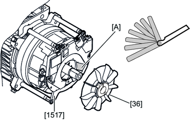
- Push the encoder module [1517] onto the shaft end.
- Push the fan [36] with bushing and pole ring onto the shaft end.
- Center the encoder module [1517] with the centering ring [1920] radially to the shaft.
- Fasten the encoder module [1517] with 3 screws [1518] on the rear endshield or, if applicable, using 3 screws [1518] on the hexagonal spacers [1520] that are fastened to the brake endshield.
- Tightening torque 2.5 Nm
- Remove the fan [36] with bushing and pole ring from the shaft end and remove the centering ring [1920].
- Push the fan [36] with bushing and pole ring onto the shaft end.
- To set a clear span of 0.9 mm between the pole ring surface and the base of the notch, insert a 0.9 mm feeler gauge into the notch [A].
- Tighten the clamping screw [1160].
- DR..71 – 100: Tightening torque 1.2 Nm
- DR..112 – 132S: Tightening torque 3.3 Nm
- Route the encoder cable in the terminal box in such a way that it is not crushed or improperly subjected to stress.
- Remove the protective cover of the M23 plug connector [1525] on the inside of the terminal box.
- Plug the socket contact of the encoder cable onto the connector on the board.
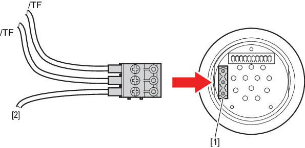
- Connect the shielding of the encoder cable [2] and, if applicable, the temperature probe /TF to the screw terminal.
- Insert the screw terminal with the connection side facing outwards into the plug connector [1] on the printed circuit board.
- Install the protective cover of the M23 connector [1525] on the inside of the terminal box.
- Connect the supply voltage and the signal cables of the encoder module [1517] to the connection unit [1522].
- Check the visual feedback of the status LED for the encoder module [1517].
- LED lights up green: The encoder module [1517] has been installed correctly and you can continue with the assembly process.
- LED lights up red: Switch off the supply voltage. Set the distance of 0.9 mm between the encoder module [1517] and the pole ring again. Switch the supply voltage back on. If the status LED still lights up red, contact the SEW-EURODRIVE Service department.
- Mount the terminal box cover [132] using the screws [123] (4 × M5 SW8).
- Tightening torque 4 Nm
- Mount the fan guard [35] with the screws [22].
- For plastic guard: Tightening torque 2 Nm
- For metal guard: Tightening torque 3.3 Nm
- Mount the forced cooling fan [170] if applicable.