Signal characteristics
The course of the signals is calculated as follows:
Vref = A × sin (ωexciter × t) |
Vcos(t) = A × ü × sin(ωexciter × t) × cos(p × α) |
Vsin(t) = A × ü × sin(ωexciter × t) × sin(p × α) |
p × α = arctan (Vsin / Vcos) |
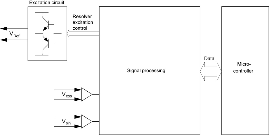
Vref | Reference voltage |
Vcos | Output voltage 1 of the stator |
Vsin | Output voltage 2 of the stator |
A | Amplitude of the input voltage |
ωexciter | Angle frequency of Ve |
α | Rotor angle |
ü | Gear ratio |
p | Number of pole pairs of the resolver |
The amplitudes of voltages Vsin and Vcos change based on the position of the rotor and are each fed to the evaluation unit via a differential amplifier. The differential amplifiers filter out interference signals (common mode interference) on the isolated track signals Vsin and Vcos.
The current mechanical position can be determined from the scanned track signals:

The following graphic provides an overview of the main hardware structure of a resolver evaluation, which operates according to the scanning process.