Operating principle
At the start of the power-on process, the absolute encoder assembly determines the absolute position. The inverter for synchronous motors can use this to calculate the commutation information. The inverter reads this position information via an RS485 connection (parameter channel) and sets a counter reading. Based on this absolute value, the position changes are recorded via the tracks of the sin/cos encoder and analogously transferred to the inverter via the process data channel. Additional queries of the absolute position are then only performed cyclically for plausibility monitoring.
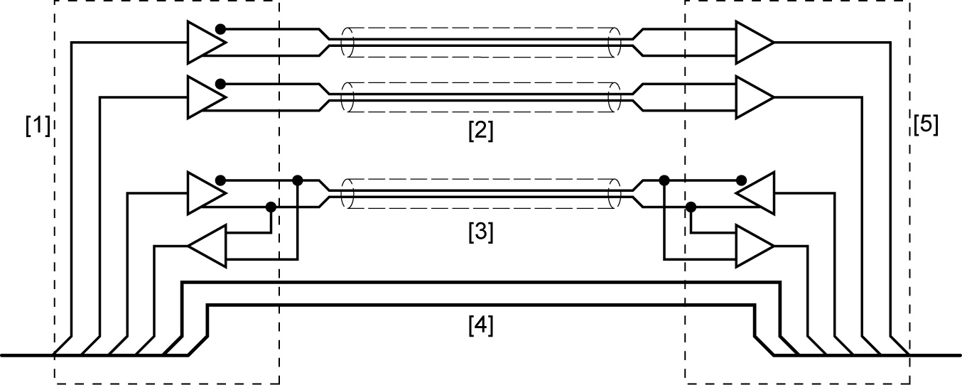
[1] Encoder systems |
[2] sin/cos signal |
[3] RS485 parameter channel |
[4] Supply voltage |
[5] Inverter |
An inverter with an asynchronous-serial interface receives both the position information and the time period for which this position is valid via the parameter channel. In parallel, the incoming analog signals (sin/cos signals) are constantly received and counted on the process data channel.
The encoder can be optionally designed as a single or multi-turn variant. Single-turn means that the absolute position information always refers to only one revolution. The multi-turn variant of the encoder can also provide information about the number of revolutions (typically e.g. 4096) via downstream code disks rotating at a reduced ratio or by using an electronic revolution counter. Thus, depending on the inverter, an encoder overflow occurs, e.g. after the maximum number of encoder revolutions, which is counted in the inverter's non-volatile memory (NVM). Up to 256 encoder overflows are saved (with 4096 revolutions). If the voltage at the supply pins falls below a limit value (e.g. in the event of a power failure), the NVM detects this and the data is saved in non-volatile memory.
Overflow example:
When powered on again, the EEPROM in the inverter provides the following values:
- The absolute value within an overflow (typically 4096 × 4096)
- The number of overflows (0 – 255)
If the drive that is close to an overflow is moved beyond the encoder overflow point after removing the supply voltage, then there will be a discrepancy between the recorded and the saved absolute values when powered on again. The encoder electronics then corrects the saved values automatically with the recorded values.
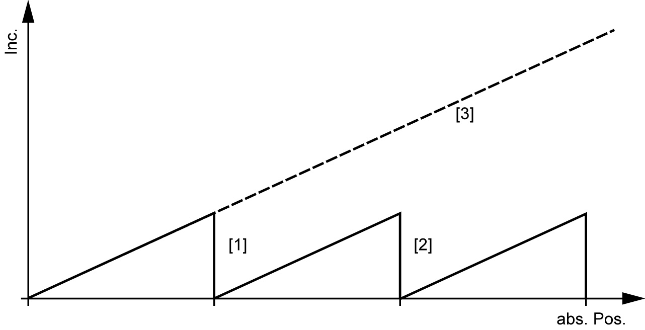
[1] 1st encoder overflow |
[2] 2nd encoder overflow |
[3] Absolute position viewed by the user |
The encoder overflows are also counted in the inverter, which can be used to determine the absolute position.
The user does not see the actual encoder overflows; they are saved in the inverter. As a result, the encoder with an asynchronous-serial interface is a true absolute encoder.
