EMC-compliant installation
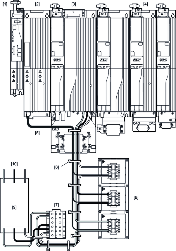
The following representations of the inverters are exemplary.
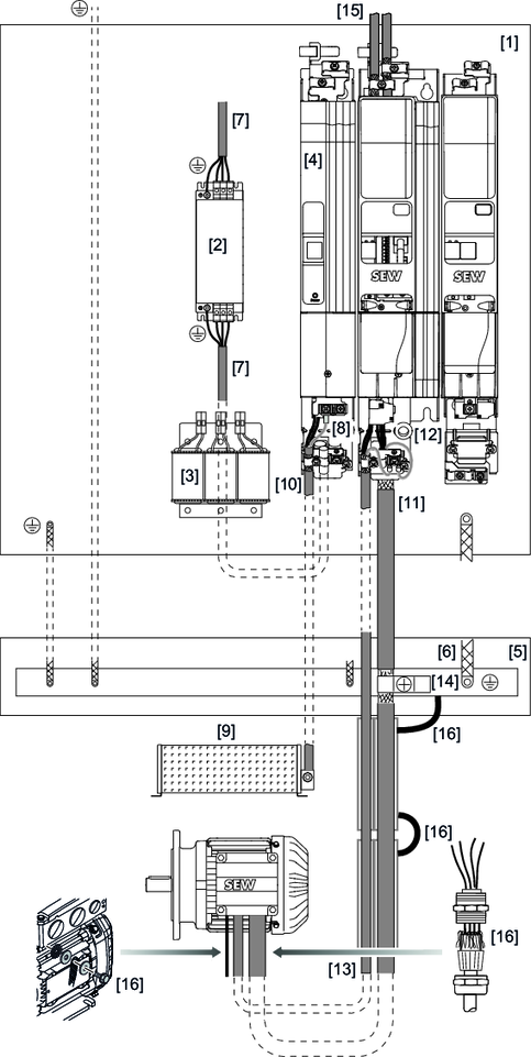
[1] | Galvanized mounting plate | [9] | Braking resistor |
[2] | Line filter | [10] | Braking resistor cable |
[3] | Line choke | [11] | Motor cable |
[4] | Inverter | [12] | Power shield plate at the axis module |
[5] | PE bar | [13] | Brake cable |
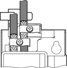
[6] | HF connection of PE bar/mounting plate | [14] | Grounding clamp |
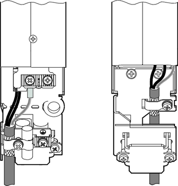
[7] | Supply system cable | [15] | Electronics shield plate |
[8] | Power shield plate at the power supply module | [16] | HF connection |
The information in this chapter will help you to optimize the system with respect to electromagnetic compatibility, or to eliminate already existing EMC interferences.
The notes in this chapter are not legal regulations, but rather recommendations for improving the electromagnetic compatibility of your system.
For further notes on EMC-compliant installation, refer to the publication Drive Technology – Practical Implementation, edition "EMC in Drive Technology – Basic Theoretical Principles – EMC-Compliant Installation in Practice".