SEW-EURODRIVE EKS energy storage unit
The diagnostic interface of SEW‑EURODRIVE’s own EKS energy storage units can be read directly from the respective device (MDP92A, MDE90A) so that no additional I/O modules are required.
Do the following to monitor and transmit the temperature:
- The diagnostic interface is connected to the respective device in accordance with the electrical wiring diagram (see "Power and Energy Solutions" product manual).
- In MOVISUITE®, open the configuration menu "Energy storage" > "Local storage interface" in the software module configuration.
- Activate the monitoring of the external error signals.
- Select the sensor type (e.g. EKS A) in the "Analog temperature sensor input"
section. - The temperature sensor can be connected directly to the MDP92A/MDE90A.
- In the "Temperature monitoring" section, set the minimum temperature, the maximum temperature, and a hysteresis.
- The diagnostic interface is automatically linked to the additional function StorageMonitor. Additional programming is not required and the diagnostics data is available to the user on the MOVI-C® CONTROLLER.
- Update the configuration data of the MOVI-C® CONTROLLER.
- The changed parameters can be read from the device and imported into the software module.
- Storage modules that are imported via the device interface are automatically assigned the stack ID 254.
- The storage unit can be read via the following user interface:
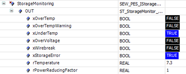
Explanation of the example:
The energy storage unit reports a general energy storage error via xStorageError (undertemperature in the case of the SEW EKS).
The SEW EKS storage unit transmits a temperature value that represents the maximum of all temperatures measured in the connected energy modules. There is also wire break monitoring and an error bit that indicates overvoltage.
The control system evaluates the temperature and also issues error and warning messages as soon as the temperature has risen above a maximum threshold or fallen below a minimum threshold. A hysteresis value is available for monitoring the maximum temperature, so that a prewarning is triggered if the maximum temperature minus the hysteresis value is exceeded.
Additional information about parallel operation
With the SEW-EURODRIVE EKS energy storage unit, the storage diagnostics data is read in combination via one interface and the result is output as an analog signal with a level between 0 V and 5 V as one diagnostic input per signal. This means that only the memory space of one energy module is required for the event bits. However, this circuit is limited to a maximum of 24 energy modules. If more modules are connected to each other, a second diagnostic chain must be formed. This can then be connected to one of the lower-level devices, but not to the master device. Event bits are not mirrored in the ParallelMode node, but errors and warnings are applied and storage monitoring is thus ensured. If storage error messages are actively suppressed (possible if the energy storage unit is not connected), these error messages are also hidden. With the exception of the event bits, the function corresponds to the storage diagnostics on the master device. The 2nd diagnostic chain to the master device via separate IO modules will continue to work and is in fact the better solution, as it offers a display option for the events.
