Operating modes
The following table shows the operating modes available in the operation of the software module. The following chapters provide a cycle diagram for each operating mode to help you better understand the operating principle as well as the process sequence with a description of the signal states.
INFORMATION

For operating function block FCB 12, the configuration settings made in the MOVISUITE® configuration apply.
Operating mode | Decimal | Description |
|---|---|---|
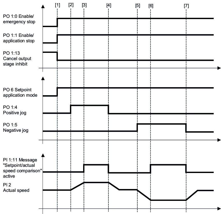
Jog mode | 100 | Position-controlled jogging (FCB 10) |
101 | Speed-controlled jogging (FCB 10) | |
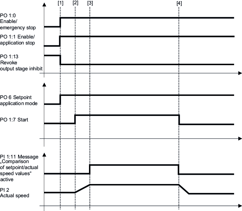
Speed control | 200 | Speed control (FCB 10) |
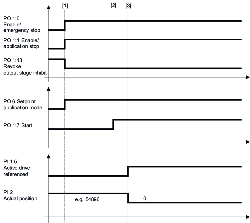
Referencing mode | 300 | Reference travel – offset via parameter (FCB 12) INFORMATION: Only available for use with real axes. |
301 | Reference travel – variable offset (FCB 12) INFORMATION: Only available for use with real axes. | |
310 | Central reference travel – offset via parameter (FCB 10) INFORMATION: Only available for use with real axes. | |
311 | Central reference travel – offset via parameter (FCB 10) INFORMATION: Only available for use with real axes. | |
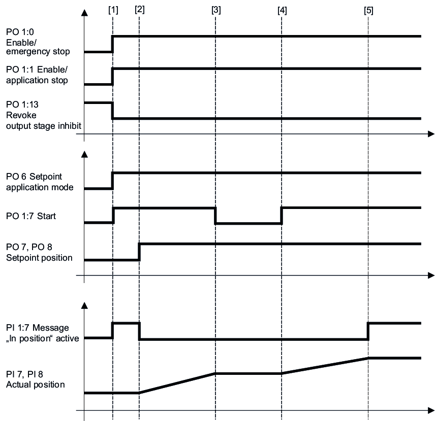
Positioning mode | 400 | Absolute position control (FCB 10) |
401 | Relative position control (FCB 10) | |
Automatic | 1400 | "Flying saw – cut length control" |
1402 | "Flying saw – cut mark control" |
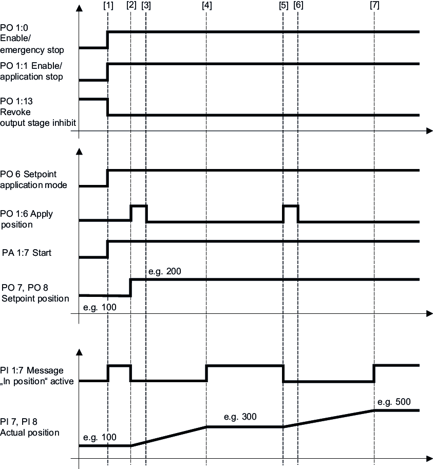
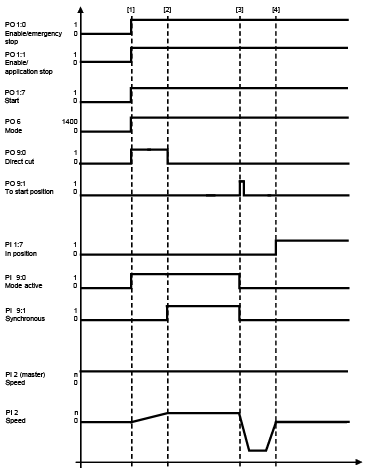
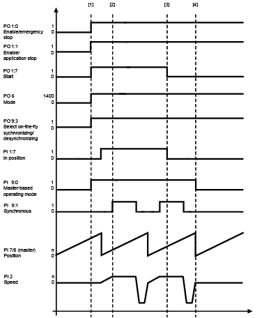
The following chapters provide a cycle diagram for each operating mode to help you better understand the operating principle. They also provide a process sequence with a description of the signals to be set and of the signal states.