Plug connector including mating connector
The following figure shows the installation height including mating connector and bending radii of the customer-side plug connectors in conjunction with prefabricated cables.
For more information, refer to the product manual > chapter "Electrical installation" > Plug connectors".
INFORMATION

The dimensions of the mating connector are examples. Deviations are possible depending on the manufacturer.
The following table shows the total height for the different drive units. Allow for a minimum installation clearance so that installation of the plug connectors is guaranteed
Gearmotor | Xh in mm |
|---|---|
DCA63.. | 118 |
F.02DCA63.. | 199 |
F.03DCA63.. | 234 |
W.02DCA63.. | 132 |
W.03DCA63.. | 146 |
KNZ63DCA63.. | 118 |
PNZ63DCA63.. | 118 |
DCA80.. | 136 |
F.03DCA80.. | 234 |
W.03DCA80.. | 155 |
PNZ80DCA80.. | 136 |
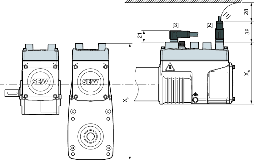
[1] | Bending radius |
[2] | "Straight" M12 plug connector design |
[3] | "Angled" M12 plug connector design |
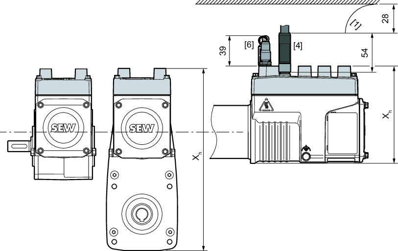
[4] | "Straight" M12 Power plug connector design |
[6] | STO jumper plug M12 |
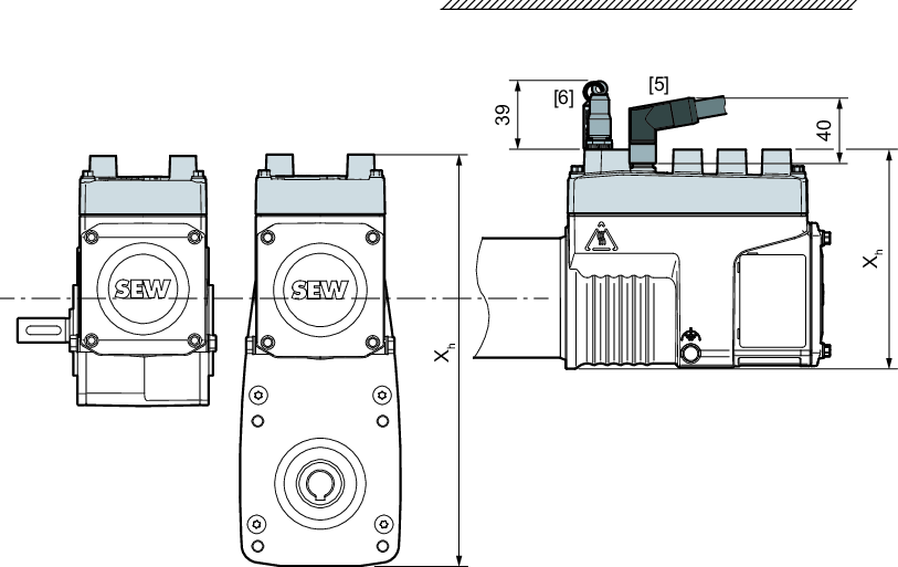
[5] | "Right-angle" M12 Power plug connector design |
[6] | STO jumper plug M12 |
