Chamfers on hollow shafts
The following figure illustrates the hollow shaft chamfers of gear units:
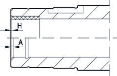
Dimension table for the chamfers of the F.., K.., S.., and W.. gear units:
Gear unit | Design | |
|---|---|---|
with hollow shaft (A) | with hollow shaft and shrink disk (H) | |
W..10 | 1.5 × 30° | - |
W..19, W..20, W..30 | 2 × 30° | – |
F..27 | 2 × 30° | 0.5 × 45° |
K..19, W..29 | 2 × 30° | 0.5 × 45° |
K..29, W..39 | 2 × 30° | 0.5 × 45° |
F../K../S..37 | 2 × 30° | 0.5 × 45° |
K..39, W..49 | 2 × 30° | 0.5 × 45° |
F../K../S..47 | 2 × 30° | 0.5 × 45° |
K..49, W..59 | 2 × 30° | 0.5 × 45° |
S..57 | 2 × 30° | 0.5 × 45° |
F../K..57 | 2 × 30° | 0.5 × 45° |
F../K../S..67 | 2 × 30° | 0.5 × 45° |
F../K../S..77 | 2 × 30° | 0.5 × 45° |
F../K../S..87 | 3 × 30° | 0.5 × 45° |
F../K../S..97 | 3 × 30° | 0.5 × 45° |
F../K..107 | 3 × 30° | 0.5 × 45° |
F../K..127 | 5 × 30° | 0.5 × 45° |
F../K..157 | 5 × 30° | 0.5 × 45° |
KH167 | – | 0.5 × 45° |
KH187 | – | 0.5 × 45° |
