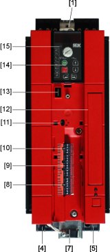
Sizes 1 / 2S / 2

[1] | X1: Power supply connection 3-phase: L1 / L2 / L3 / PE screw |
[2] | X4: Connection for DC link coupling –UZ +UZ |
[3] | X3: Braking resistor connection R+ / R– / PE |
[4] | Electronics shield clamp |
[5] | X2: Motor connection U / V / W / PE screw |
[6] | X17: Safety contact for safe stop (only 400 / 500 V) |
[7] | X13: Digital outputs |
[8] | X12: Digital inputs |
[9] | X10: Analog input |
[10] | Switch S11 for V-mA toggle analog input |
[11] | Space for option card (cannot be retrofitted) |
[12] | Connection for optional communication / analog module |
[13] | Optional keypad, inserted |
[14] | Status LED (visible without optional keypad) |
