Fixed setpoints
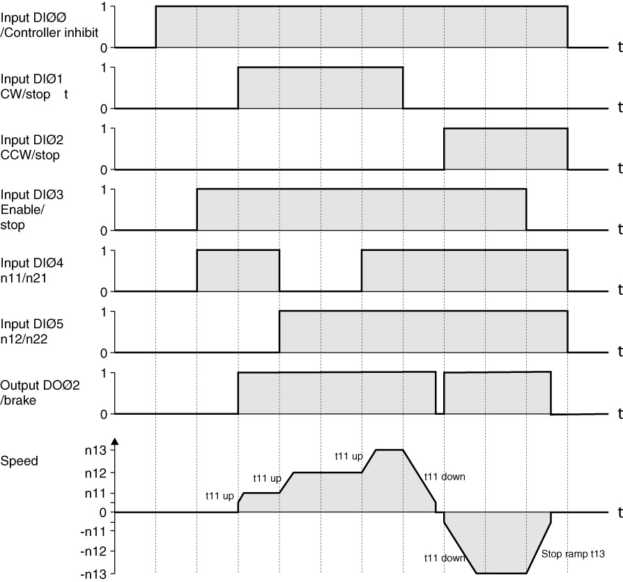
The following table shows which signals must be present on terminals X12:1 – X12:6 (DIØØ – DIØ5) when the "unipolar/fixed setpoint" setpoint is selected (P100) in order to operate the drive with the fixed setpoints. This terminal assignment is an example. It can be changed via parameters P601 – 608. CW/stop DIO1 is permanently assigned.
Function | X12:1 (DIØØ) /Controller inhibit No default setting | X12:2 (DIØ1) CW/stop Fixed assignment | X12:3 (DIØ2) CCW/stop | X12:4 (DIØ3) Enable/Stop | X12:5 (DIØ4) n11/n21 | X12:6 (DIØ5) n12/n22 |
|---|---|---|---|---|---|---|
Controller inhibit | 0 | X | X | X | X | X |
Stop | 1 | X | X | 0 | X | X |
Enable and stop | 1 | 0 | 0 | 1 | X | X |
Clockwise at n11 | 1 | 1 | 0 | 1 | 1 | 0 |
Clockwise at n12 | 1 | 1 | 0 | 1 | 0 | 1 |
Clockwise at n13 | 1 | 1 | 0 | 1 | 1 | 1 |
Counterclockwise at n11 | 1 | 0 | 1 | 1 | 1 | 0 |
0 = 0 signal 1 = 1 signal X = Not relevant |
The following travel cycle shows by way of example how the drive is started with the assignment of terminals X12:1 – X12:6 and the internal fixed setpoints. Digital output X10:2 (DOØ2 "/Brake") is used for switching brake contactor K12.

INFORMATION

