Operating modes
INFORMATION

A requirement for all operating modes is that the axes are enabled via the enable bits Enable/emergency stop and Enable/stop at user-defined limits in the control word. For more information, refer to the chapters MOVIKIT® StackerCrane control word and Process data assignment.
The operating mode is defined via process data word for all subordinate axes of the software module. The operating mode is changed over in the idle state.
The software module provides the following operating modes:
Operating mode | Dec | Description |
|---|---|---|
Default | 0 | Enabling or disabling the axes |
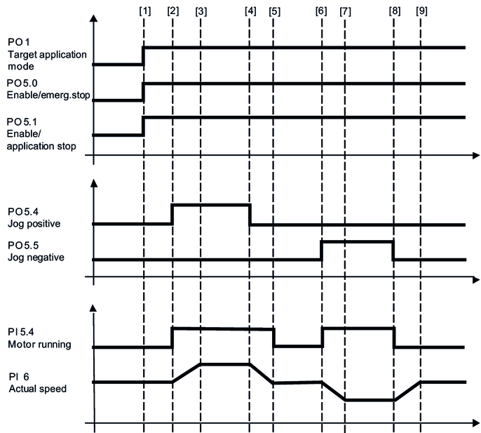
Jog mode | 100 | The axes are moved manually using the jog positive, jog negative bits and the corresponding dynamics parameters. |
Cam jog mode | 130 | Manual movement of the axes using the Positive jog, Negative jog bits and appropriate dynamics parameters, taking the configured speed cams at the ends of the aisles into consideration. |
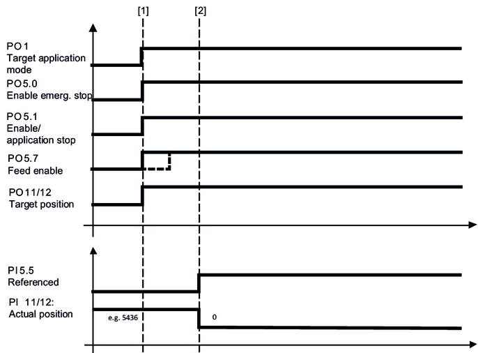
Referencing mode | 300 | A configured reference offset is written to the actual position |
301 | A reference offset specified via bus is written to the actual position | |
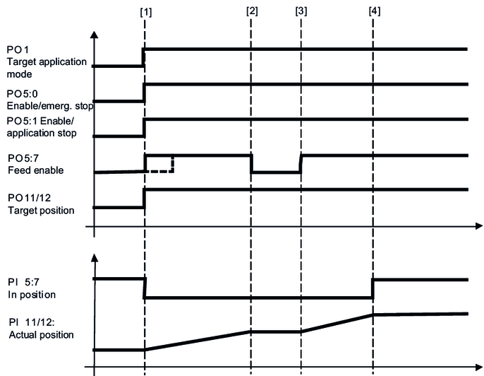
Positioning mode | 400 | Positioning of the axes is not energy optimized |
Cam positioning mode | 430 | Non-energy optimized positioning of the axes taking the configured speed cams at the ends of the aisles into consideration. |
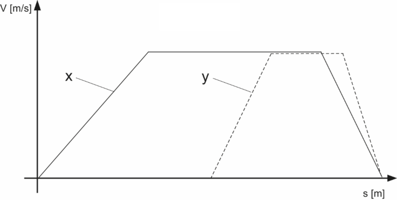
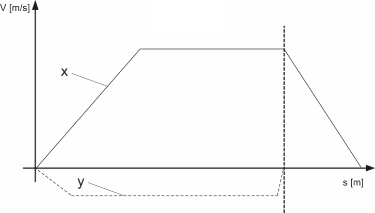
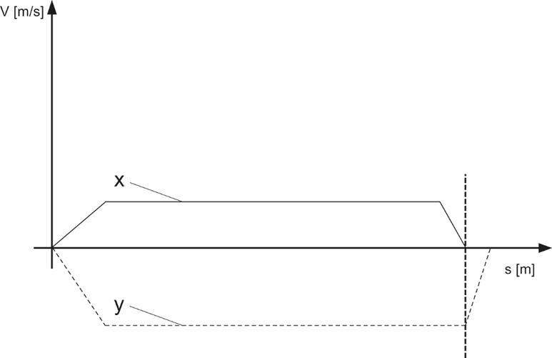
Energy-optimized XY positioning | 1200 | Energy-optimized positioning of the axes |
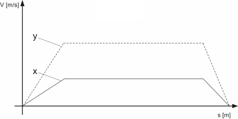
Mechanics-optimized positioning | 1210 | Diagonal positioning by reducing the speed of an axis. |
External brake test | 1300 | Preparing the external brake test The brake test is configured via safety card and is controlled using the safe bus or safe inputs. |
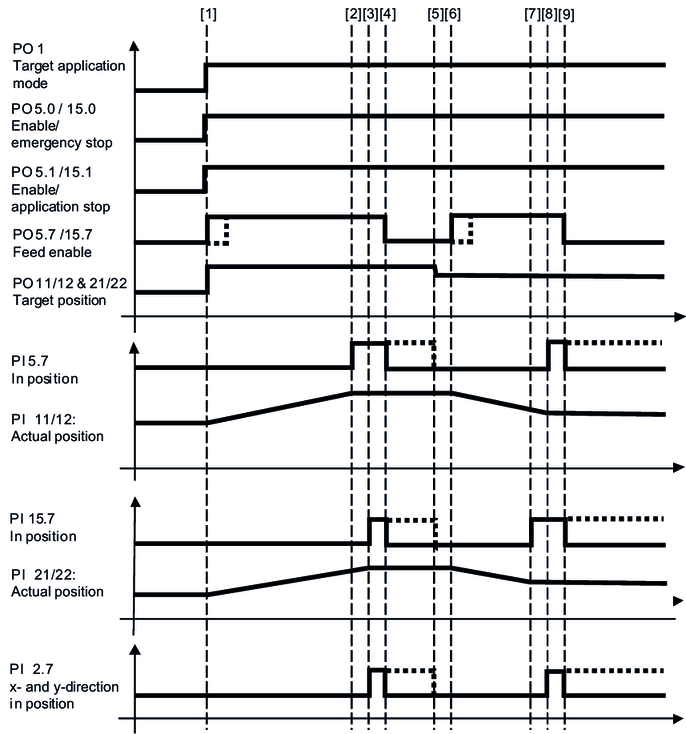
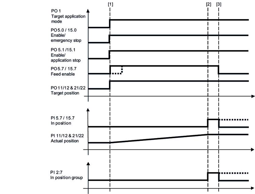
The following chapters provide a cycle diagram for each operating mode to help you better understand the operating principle. They also provide a process sequence with a description of the signals to be set and of the signal states.