Hardware limit switch
The following diagram and the corresponding explanation illustrate the behavior of the software module when using hardware limit switches in connection with the "Skew priority" operating mode.
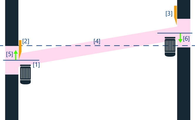
The left drive with actual position [1] has reached its hardware limit switch [2]. However, the hardware limit switch of the right drive [3] has not yet been reached due to a non-symmetrical assembly despite a skew error. If the error is now acknowledged due to the reached limit switch [2], the skew error is compensated if it is in the skew error window.
When compensating the skew error, the left drive moves upwards toward the center line [4] by the position difference [5] and the right drive moves downwards toward the center line [4] by the position difference [6]. This means that the left drive continues to move into its hardware limit switch [2] without issuing another error.
However, if the hardware limit switch [3] has not yet been triggered instead of the scenario shown above and this hardware limit switch is approached due to skew compensation, a fault is issued and the application is brought to a standstill.
