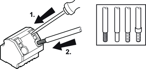
Activating terminals X3 for the braking resistor
Adhere to the following sequence when actuating the X3 terminals for the braking resistor:
❮
❯
MOVIMOT® flexible DSI
Language
Deutsch
English
Français
Español
Brasileiro
汉语
SEW-EURODRIVE
Home
Electrical installation
Installation instructions
Activating terminals X3 for the braking resistor