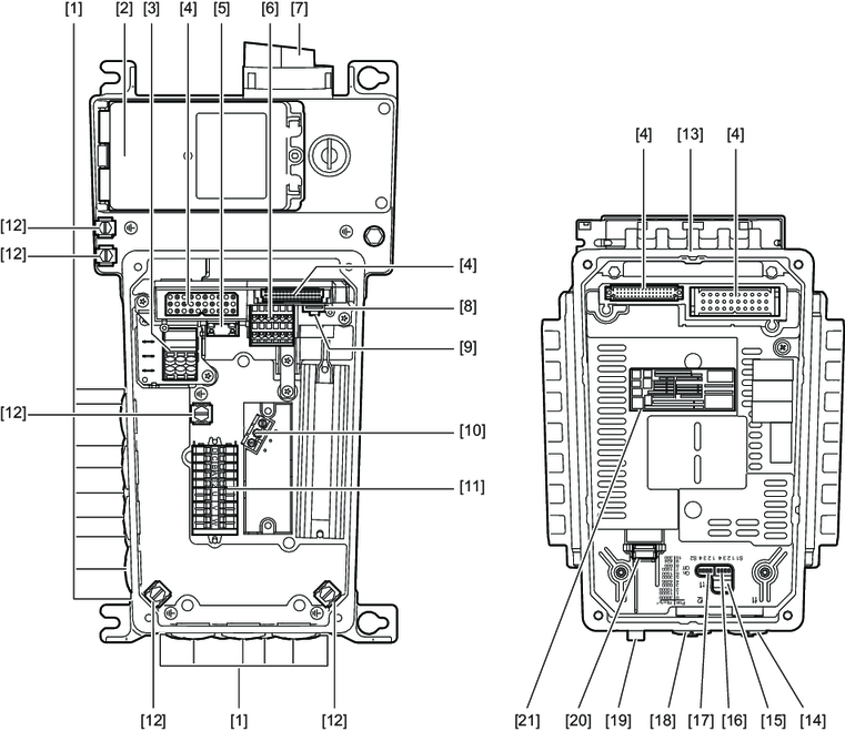
Connection box and electronics cover (internal) MMF32 design
The following figure shows the connection box and the bottom side of the electronics cover:

[1] | Cable glands | [12] | Screws for PE connection |
[2] | Front module | [13] | Electronics cover |
[3] | Connection line L1, L2, L3 | [14] | Potentiometer f1 (underneath the screw plug) |
[4] | Plug connector connection | [15] | Potentiometer t1 |
[5] | Braking resistor connection | [16] | DIP switches S1/1 to S1/4 |
[6] | Electronics terminal strip | [17] | DIP switches S2/1 to S2/4 |
[7] | Maintenance switch | [18] | Potentiometer f2 (underneath the screw plug) |
[8] | Engineering interface | [19] | Plug connector |
[9] | MOVILINK® DDI connection | [20] | Replaceable memory module |
[10] | Internal terminals | [21] | Electronics cover nameplate |
[11] | Motor and brake connection |
|
|