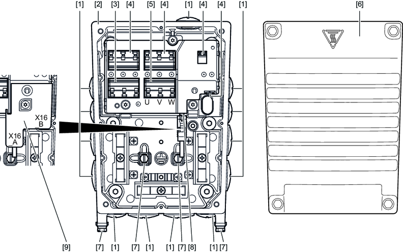
MGF..2-DSM-C/DI, MGF..4-DSM-C/DI and MGF..4-DSM-C/XT/DI design
The following figure shows the connection box and the cover of MOVIGEAR® classic MGF..2-DSM-C/DI with MOVILINK® DDI Slave and without encoder:

[1] | Cable glands |
[2] | Connection box |
[3] | Reserved terminals |
[4] | Terminals for internal wiring |
[5] | Terminal X2_A for motor connection U, V, W |
[6] | Cover |
[7] | Screws for PE connection |
[8] | X16_A connection for MOVILINK® DDI |
[9] | Plug connector cover (only in connection with UL) |
The connection board is identical for the drive units MOVIGEAR® MGF..2-DSM-C/DI, MGF..4-DSM-C/DI and MGF..4-DSM-C/XT/DI.