Adding scope containers
Scope containers allow access to scope recordings from the inverter. For this purpose, the software controls the scope recorder of the inverter (start, extract data) and checks on a cyclical basis whether data from a new scope recording is available.
As the scope recorder of the inverter can only be used by one instance at a time, multiple scope recordings are not possible simultaneously. If a scope recording has already been started by MOVISUITE®, the software will overwrite this access. However, it is possible to use the container to control several devices at the same time.
The scope template used can be configured directly in the software or imported from the inverter or a scope template file.
To add a scope container, proceed as follows:
- At least one device group and one endpoint have been created.
- Open the "Containers" tab.
- Click [+ Add].
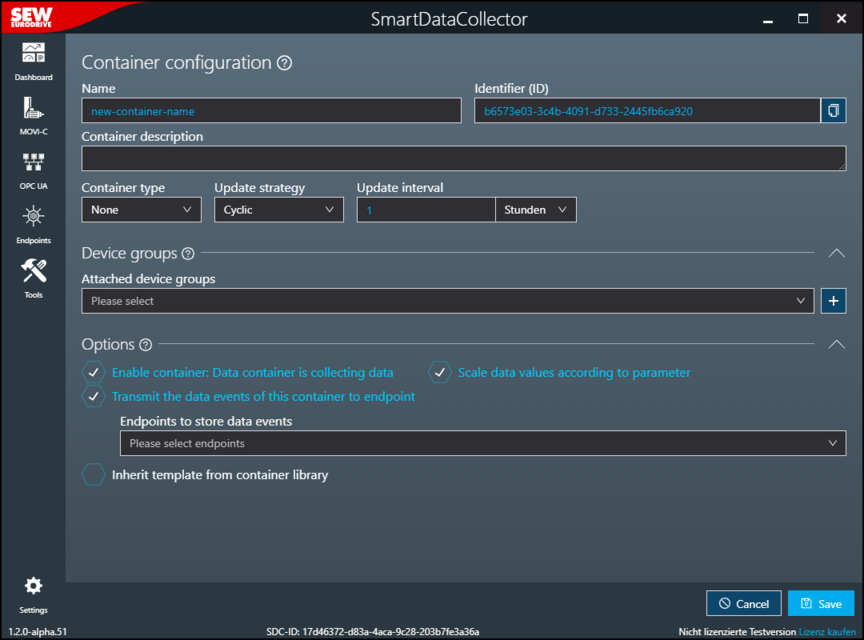
- The "Container configuration" dialog window opens.
- The container can be configured via the following setting fields:
Setting field | Description |
|---|---|
Name | Enter a name for the container. The name is used in the tool configuration process and in the file structure when storing the JSON files. |
Identifier (this is generated) | Unique identifier of the container that is generated automatically by the software and used internally for further processing. This identifier forms part of the name of the target directory on the associated endpoint. |
Container description | Add optional description text. The description text is displayed under the "Containers" tab. |
Container type | Select the container type. For a scope container, select the value "Scope". The relevant fields for the scope container are then displayed in the dialog window. |
Update strategy | Specify the update strategy of the container:
|
Update interval | Specify the update interval for cyclic data acquisition. The update interval describes the time between two successive cycles. Each cycle consists of reading and transferring data and takes about 100 ms. For example, an update interval of 5 ms results in a cyclical output interval of approx. 105 ms. The maximum value for the update interval is 31 days. |
Device groups | |
Assigned device groups | Select the device groups for data acquisition. All groups created under the "Groups" tab are available here. |
[+] button | Create a new group and assign it to this container. |
Options | |
Enable container: Data container is collecting data | Specify whether the recording of data by the container is activated immediately after saving the container configuration. |
Convert raw data into SI units | Activate the conversion of acquired raw data into SI units. INFORMATION: If you use the software in conjunction with the IoT Suite, conversion is not necessary because the conversion takes place in the IoT Suite itself. |
Transmit data events of this container to endpoint | Activate or deactivate data transmission from this container to the selected endpoints. |
Endpoints to store data events | Select one or more of the configured endpoints as the storage location for the recorded data. All entries created in the "Endpoints" menu are available here. |
Inherit template from container library | Activate the inheriting of the data model of a configured library container. Changes in the library container are automatically applied to the container. The "Inherited containers from library" edit box for selecting the library container and the "Overwrite library" choice box in the "Scope configuration" and "Trigger settings" areas are displayed. |
Inherited containers from library | Select one or more of the configured library containers to inherit the data model that is specified within. All of the entries that are created in the "Library" menu are available here. The recording channels contained in the selected library container are added to the "Recording channels" area, but cannot be edited there. |
Scope configuration | |
[Import] button INFORMATION: Only visible if "Inherit template from container library" is deactivated. | Import a complete scope configuration from a MOVISUITE® MES or an XML file or from a switched-on device. For further information, refer to chapter Scope configuration. |
Overwrite library INFORMATION: Only visible if "Inherit template from container library" is activated. | Activate the overwrite of the configuration defined in the library container. |
Sample rate | Specify the time interval between successive data samples. |
Post-trigger recording | Specify the percentage of the available recording buffer that should be filled with pre-recorded samples when the scope is triggered. |
Application index | Set the operating mode of the scope recorder.
|
Memory optimization | Activate or deactivate optimization of memory usage. |
Limitation of data points | Specify whether the number of data points should be limited. If you select "No limit", the scope cache is written completely. If you select "Strict limit", the "Maximum number of measuring points" field and the [Calculator] tool are displayed and the scope cache is only partially written according to the specified number. |
Maximum number of measuring points INFORMATION: Only visible if the "Strict limit" option is selected for "Limit data points". | Specify the maximum number of measuring points. A "calculator" is available for calculating the optimum value for the recording time or the maximum number of data points. |
[Calculator] button INFORMATION: Only visible if the "Strict limit" option is selected for "Limit data points". | Calculate the optimum value for the recording time or the maximum number of data points. For further information, refer to chapter Calculator. |
Recording time (estimate) | Generated estimate of the minimum recording time in milliseconds in accordance with the configuration above. |
Recording channels (NOTE: To save data, do not add a scope channel to more than one container) | |
[+ Add one] button | Open the "Channel" dialog window to configure and add a scope channel. In the "Channel" dialog window, set the scope channel by specifying the index, subindex, name, and channel offset, or by selecting an entry from the "Available channels" list. By activating the "Only supported" check box, only parameters that can be used as a channel for a scope recording are displayed in the "Available channels" list. The added channels can then be re-sorted in the list of recording channels using the corresponding buttons. |
Function in the [Import scope channels from JSON file] submenu | Add scope channels by importing a JSON file or a CSV file exported from Excel, for example. |
Function in the [Export scope channels to JSON file] submenu | Export the currently created scope channels as a JSON file. |
Function in the [Import channels from library] submenu | Import scope channels for data recording from a library container. Changes in the library container are automatically applied to the container. |
Trigger settings | |
Overwrite library INFORMATION: Only visible if "Inherit template from container library" is activated. | Activate the overwrite of the configuration defined in the library container. |
Delay mode for the trigger | Set the delay for a configured trigger.
|
Delay time for the trigger | Set the delay for the configured trigger. |
Activate trigger #1-#3 | Activate the desired number of triggers and use the choice boxes that appear to specify the channel name and the trigger type. Decimal and hexadecimal values can also be entered in the "Compare value" edit box. Hexadecimal values require the prefix "0x". |
Linking triggers | Connect multiple scope triggers to one another by using Boolean operators. |
Estimates | |
Estimate of the events and data transmission rates generated by the configuration. The estimate can be updated via a button. | |
Metadata | |
Advanced information about the container | Displays the scope hash |
[Calculate] button | Calculate the scope hash according to the settings made. |
