Expanding a project with additional machine modules
Example 4
Add a second conveyor belt to the basic program of the manual.
Solution
Five steps are required to add a new machine module.
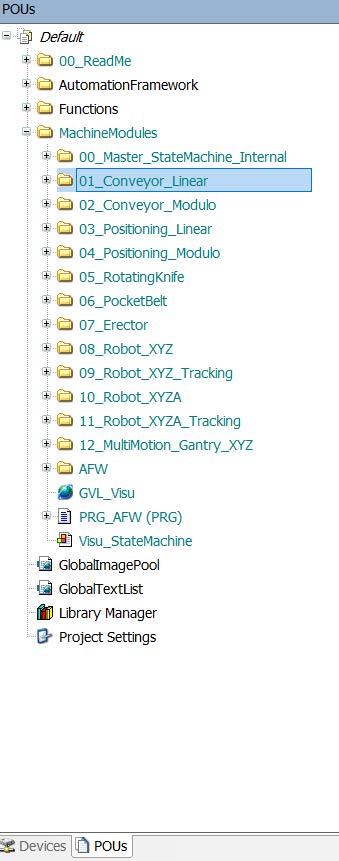
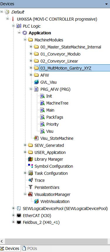
The POU folder contains all available machine modules. The code is not compiled ("exclude from build") unless it has been added to the basic program. The "Conveyor" machine module is therefore copied from the POU tab of the IEC Editor and added to the "Devices" tab under "MachineModules".
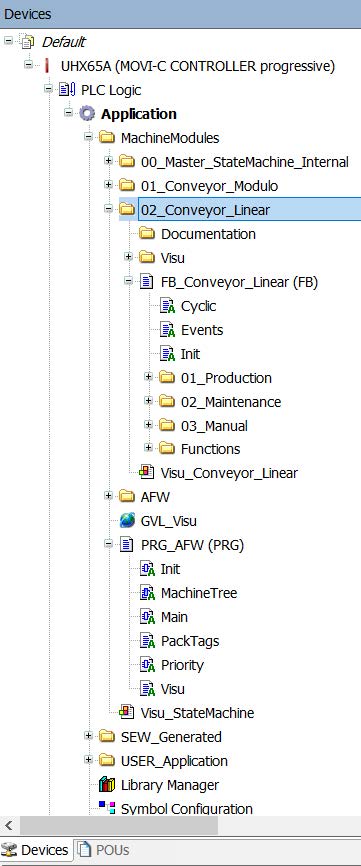
After the machine module has been added under MachineModules, it is recommended to rename it with an ascending prefix. All machine modules are arranged among one another and are detected accordingly.
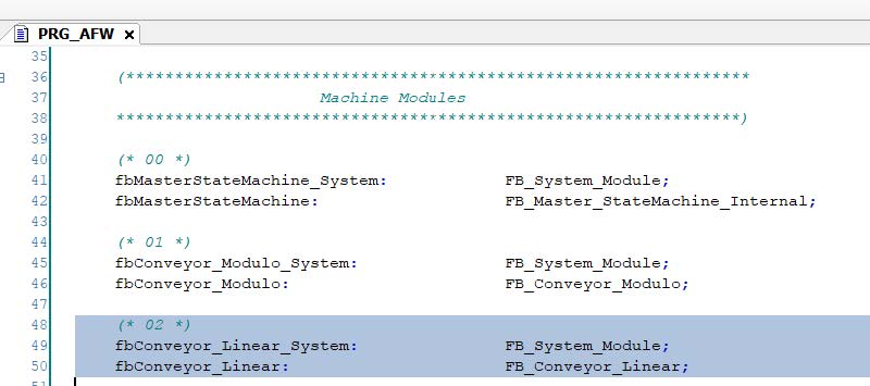
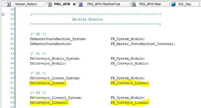
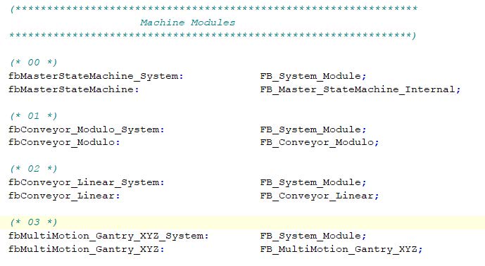
The second step is to define the new module. The definition is made directly in PRG_AFW. It is recommended to use the sample of the already existing modules and adapt the designation accordingly.
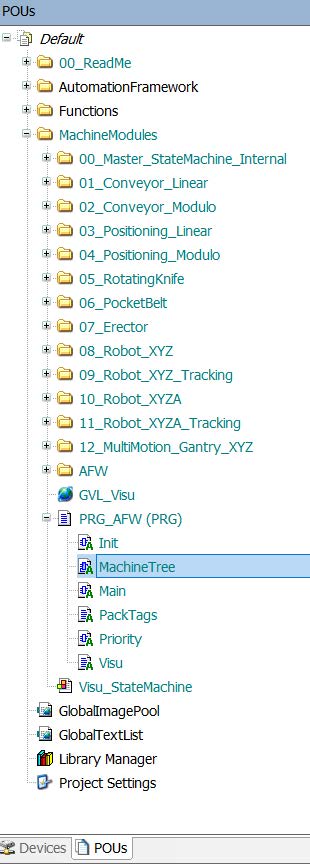
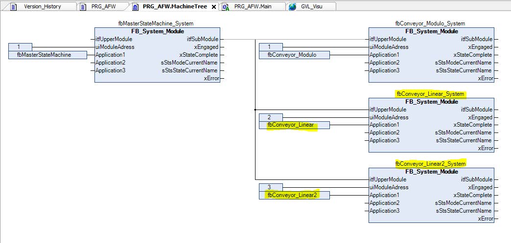
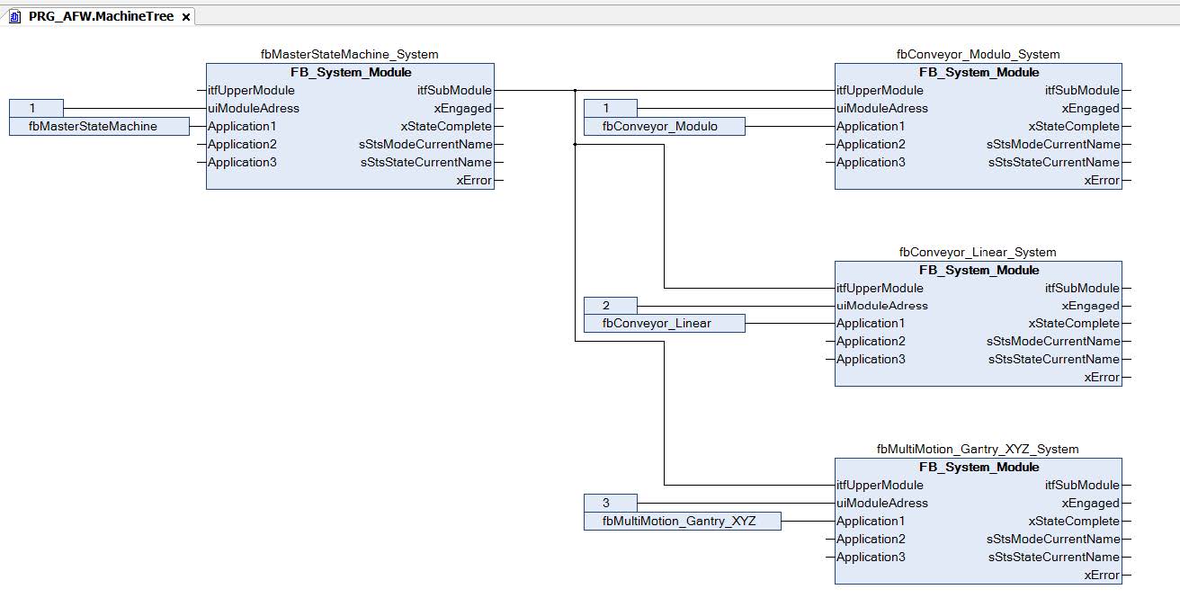
The third step is to add the new conveyor belt to the machine tree. To do so, you can open the MachineTree from PRG_AFW, which is found in the "POUs" tab, copy the "fbConveyor_System" there and add it to the MachineTree of the PRG_AFW in the "Devices" tab.
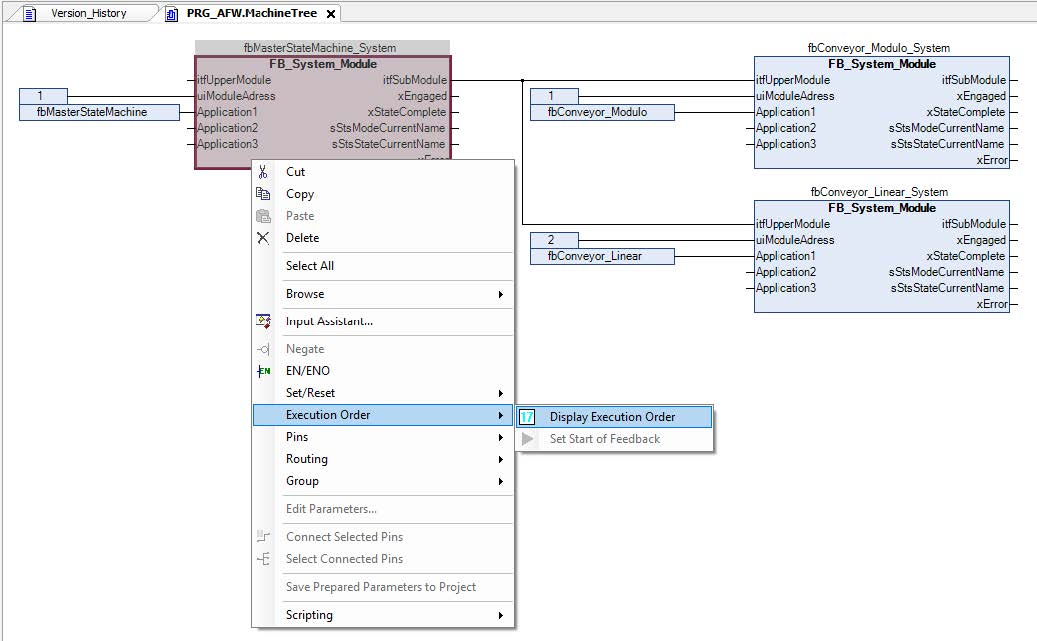
Note that it is recommended to adjust the addresses in such a way that they are counted in ascending order from top to bottom. It is important that the "fbMasterStateMachine_System" master is executed first in the execution sequence. It is recommended to execute the slaves in the same order as for addressing.
To activate the display of the execution sequence, right-click on a function block and select "Display execution order", as shown below.
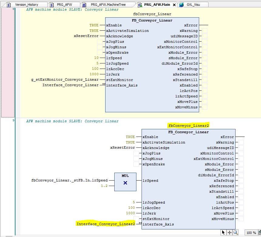
The fourth step is to assign the call of the fbConveyor in "Main" of the PRG_AFW to the "Devices" tab. Copy the call for the conveyor belt from "Main" in the "POUs" tab and add it to "Main" in the "Devices" tab.
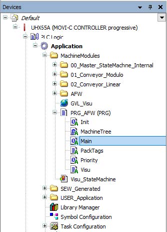
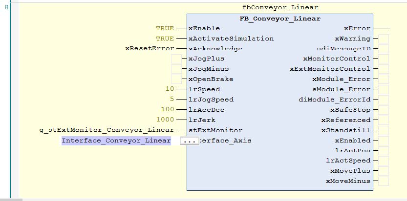
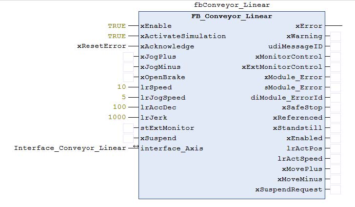
The call for "FB_Conveyor_Linear" is added as a new network at the end of "Main".
The program is ready for execution after having performed these 4 steps. Next, the interfaces have to be adapted. The "interface_Axis" interface must be assigned to the new axis that must be added to the MOVISUITE® project. Once the axis has been inserted into the MOVISUITE® project, the IEC project must be updated so that the axis is available in the program.
The new interfaces can now be found under SEW_GWL and SEW_GWL_Internal:

Finally, the new visualization structure must be added to GVL_Visu to be able to use the external HMI. If no HMI is to be used, the input can be disabled and the program can run without an external monitor.
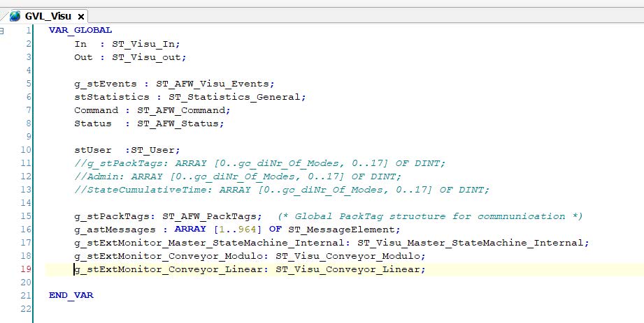
A fully functional machine module has been added to the project and can now be used. For less complex machine modules such as the conveyor belt, the work is now finished. The machine can be operated; additional inputs may have to be assigned.
Example 5
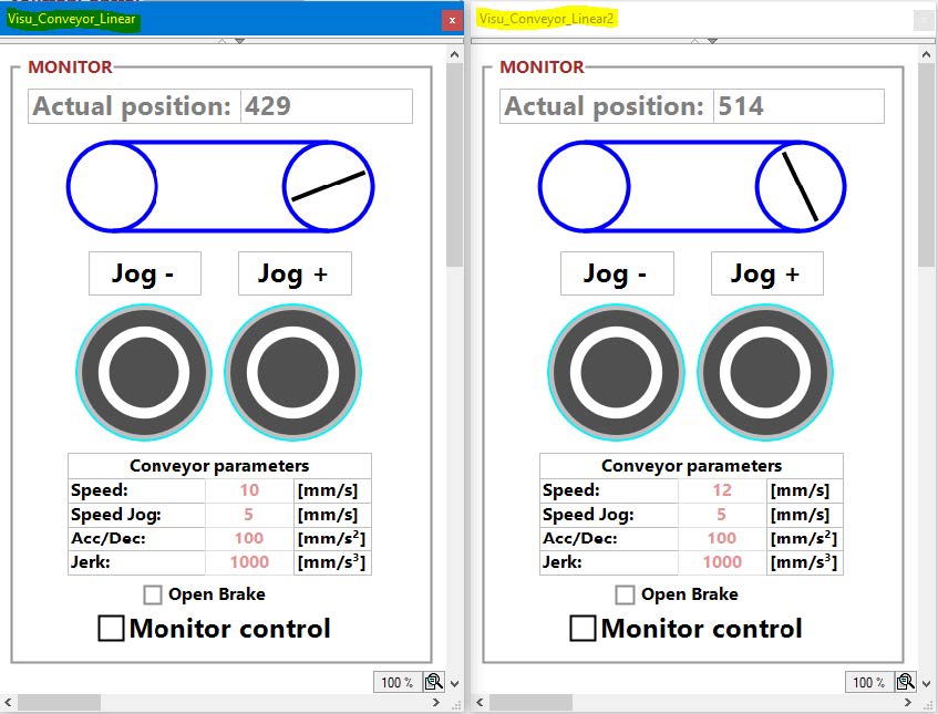
Insert a second linear conveyor belt in addition to the conveyor belt added in example 4. Create a work monitor for the second linear conveyor belt.
Solution
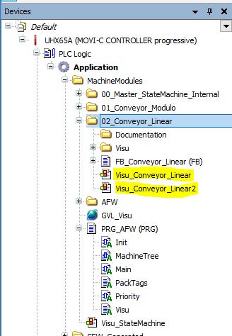
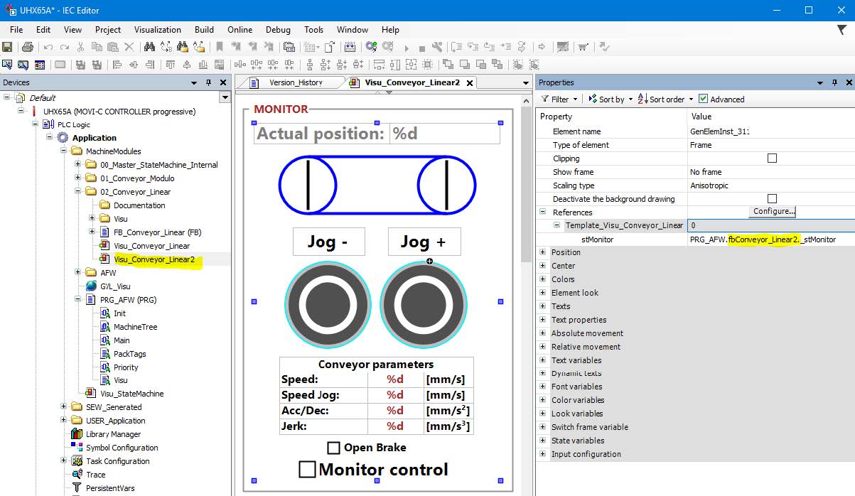
For the monitor to work for a specific conveyor belt, the reference to this conveyor belt must be set. The monitor is not necessary to operate the machine module but simplifies machine diagnostics and testing. In Visu_Conveyer_Linear2, the name can be changed under "References".
Example 6
In order to demonstrate the more complex AppType1, a robot is added to the basic program in this exercise.
Solution
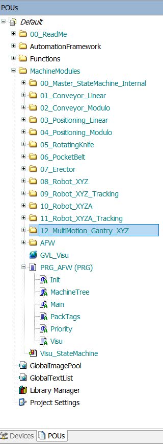
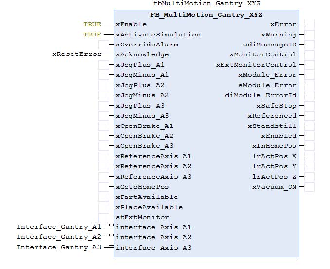
The machine module for the robot is added in the same way as the conveyor belt. The entire folder with MultiMotion_Gantry_XYZ is copied from the function blocks and added to the machine modules in the "Devices" tab.
The second step is to define the new module that must be declared in PRG_AFW. It is recommended to also copy this part of the code from the PRG_AFW of the POE and paste it into the PRG_AFW of "Devices".
The third step is to add fbRobotGantry_XYZ to the machine tree. It is recommended to copy the structure from the existing MachineTree to the POEs and adding it to the MachineTree under "Devices". Adhere to the execution sequence and ensure that the addresses are correct.
The robot FB must be called in Main. Use PRG_AFW under POU as a template, copy the FB call and paste it into "Main" in the "Devices" tab.
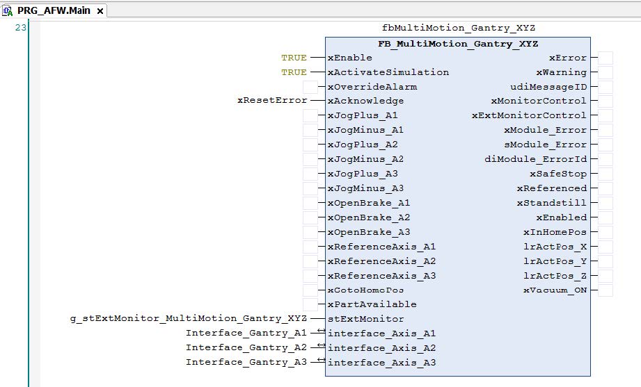
The Robotics machine module has now been successfully added and only the interface needs to be operated. If the gantry with its axis has been added to the MOVISUITE® project and the IEC project has been updated, the interfaces can be found under SEW_GVL and SEW_GVL_Internal.
This means that a robot is now also part of the project. The robot can be used for pick and place tasks and automatically follows the same sequence as the 2 conveyor belts, which are controlled by the master module fbMasterStateMachine.
Example 7
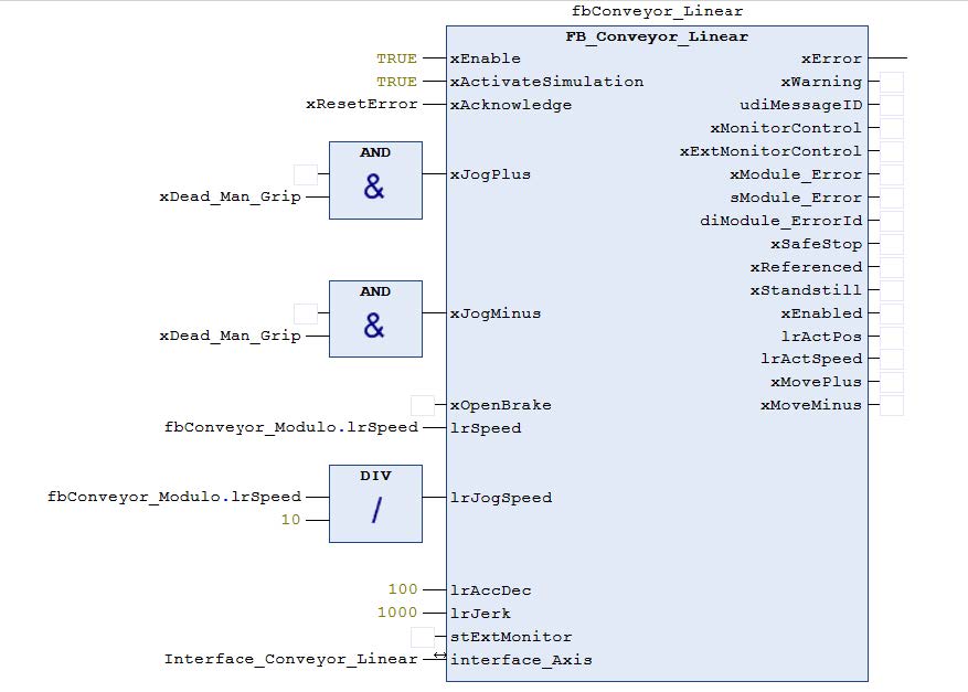
Change the JogSpeed entry so that it is always 10% of the speed of Conveyor_Modulo. Add a Dead_Hand_Grip variable and change the logic in "Main" so that JogPlus and JogMinus can only be executed if the Dead_Man_Grip variable = TRUE.
Solution
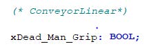
In PRG_AFW, a new variable is declared that is used for Dead_Man_Grip.
These variables and simple logical functions are used to change the input for the FB call for the conveyor belt. This has the advantage that the code is easy to understand. As long as the logic is not too complicated, it is recommended to use this type of operation directly in "Main".
Example 8
Change the fbMultiMotion_Gantry_XYZ machine module in the basic program. This machine module checks whether the product is in the removal position before the robot attempts to remove it. It is not checked whether the position for depositing the product is free. Extend the existing machine module in such a way that an input indicates whether the storage position is free. If the storage position is free, the robot should deposit the product. If the position is not free, the robot should move to the home position and wait there until the position is free.
Solution
The machine module is added to the project in the same way as described in the previous exercises. The necessary changes can be made in "production" mode, in the "execute" state.
Two new variables are added. One variable is used as input to indicate whether the place position is free. The other variable is used as an internal flag to check whether the next movement from the home position to the place position or to the pick position is to be performed.
These variables are then used in the pick sequence:
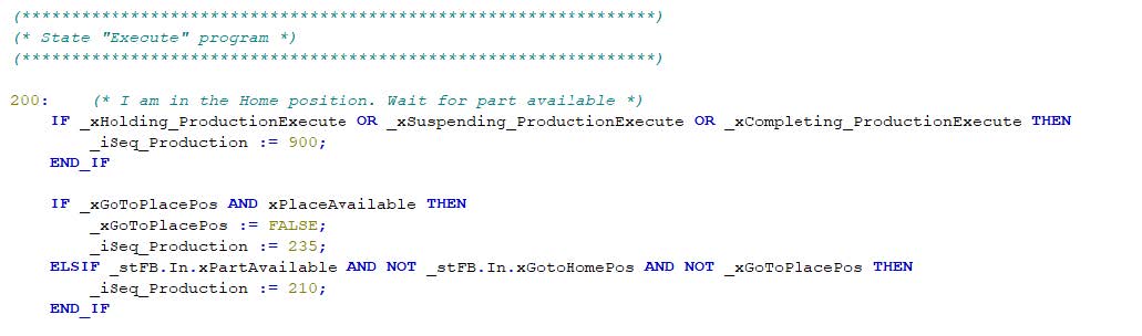
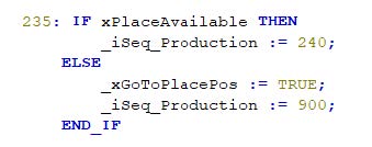
When the product has been removed, a check is performed whether the product can be placed. When this check has been performed, a new step is inserted between 230 and 240.
These two changes to the program, both of which can be made in only one mode and only one state, have extended the program to include a check of the local movement.
In "Main", an input variable is added to the call for the robot.
Example 9
Delete the robot_XYZ and a conveyor belt from the base project so that only the conveyor belt and the MultiMotion_Gantry_XYZ will be left. Change the suspend branch in such a way that the conveyor belt is stopped and the robot moves to the initial position if the upstream or downstream machine cannot deliver or pick up products. If the conditions for the interruption are no longer present, the machine should automatically switch to production mode. The suspend branch should only work in "production" mode.
Solution
In this case, various approaches are possible. It could be argued that the state machine is controlled by the master machine module and everything regarding the step sequence should be changed directly on the master. For example, an input could be connected to the cyclical stop, this input called "suspend" and have it displayed so that upstream or downstream machines are blocked. Two different approaches are presented below.
The first approach is chosen to obtain a simple solution. A suspend input is added to the Multimotion_Gantry_XYZ machine module and the conveyer machine module. If this input is triggered, the machine modules request a "suspend" from the master. This programming makes visible the reasons for the state change. The disadvantage is that the logic upstream of the master must be adapted for each machine module added. Another disadvantage is that the reason for the suspend is not set with the event as in the second approach.
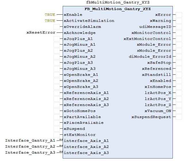
First, the "xSuspend" input and the "xSuspendRequest" output are declared and the parameters for both machine modules are updated.
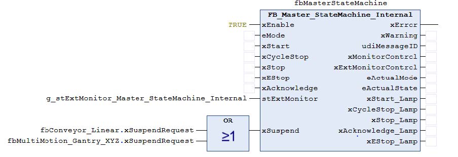
A new input is declared on the master module fbMasterStateMachine. If this input is triggered, the machine is set to the "suspend" state.
Similar changes are made to the individual machine modules. The fbMasterStateMachine is extended by 3 states in mode production and the "suspending" branch is activated. Robot_Gantry_XYZ_MuMo already has a suspend branch and is not affected. The conveyor belt is extended with actions in the affected states.
In fbMasterStateMachine "production" mode, "execute" state:
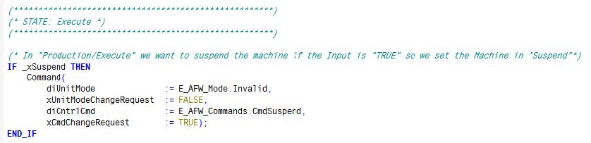
In "production" conveyor mode, "suspend" state:
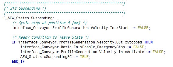
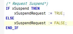
For both the robot and the conveyor belt, the input is evaluated and the output is set to "cyclic" in the program action:
A new branch has been activated with these program changes.
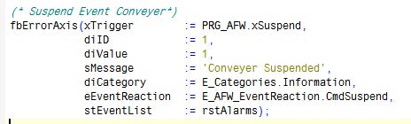
The second approach is to use the "events". In this approach, we declare the suspend variable again in PRG_AFW. This variable is now globally accessible. In a real machine this variable would be connected to a digital input, for example. This variable can be used to trigger an event. The event is triggered in FB_Conveyer under "Events".
The corresponding changes must be made in Robot_Gantry_XYZ_MuMo if a suspend event is also to be triggered there.
To exit "suspended" when the trigger is no longer present, the command must be set so that it exits "suspended" if this is the case. This is done in MasterStateMachine in "suspended" state.

To enhance readability, it is also possible to declare local variables for xSuspend as described in the previous approach.
The advantage of this approach is that the machine module responds to a suspend command. If the machine module is used in another machine, the same event would be triggered. It is important that the programmer is familiar with the AFW when using events. The events force the master to a certain state. If this is not taken into account when creating the program, unexpected reactions can occur.
