Measurement of a coordinate system
You can use the SEW_MK_Robotics.SEW_RobUserCs.CoordSysMeasurement function block to measure a coordinate system, for example the position and orientation of a workpiece or a conveyor belt in the desired reference coordinate system.
To do so, 3 points of the coordinate system to be measured from the point of view of the reference coordinate system (e.g. BASE) must be applied to the input variables Position_1/2/3.
Depending on the measurement method set (input variable eCoordSysMeasurementType), these points are either …
- the origin (input variable alrPosition_1),
a point on the positive X‑axis of the coordinate system to be measured (input variable alrPosition_2), and
a point in the XY‑plane with a positive Y‑coordinate of the coordinate system to be measured (input variable alrPosition_3). - (Measurement method P1_Origin_P2_OnXAxis_Xpositive_P3_InXYplane_Ypositive)
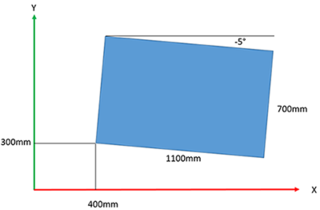
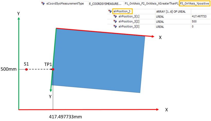
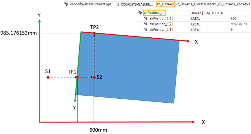
or - a point on the X‑axis of the coordinate system to be measured (input variable alrPosition_1),
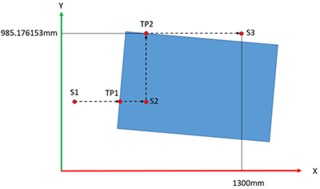
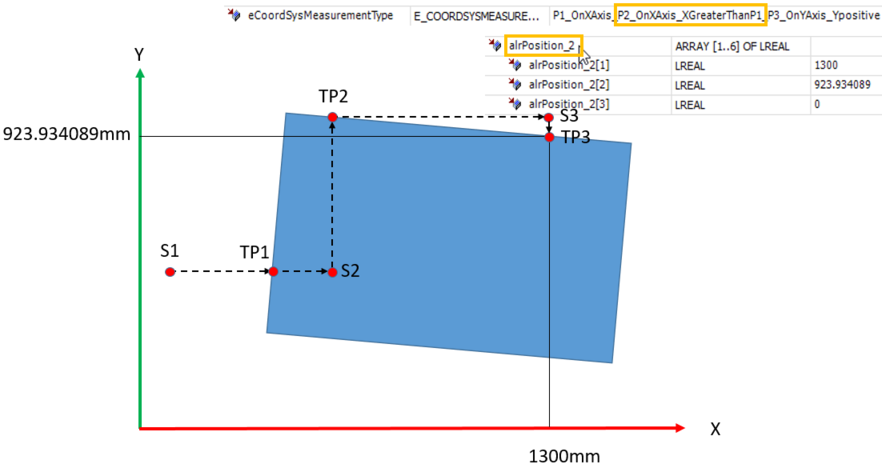
another point on the X‑axis with a larger X‑coordinate value (input variable alrPosition_2), and
a point on the Y‑axis with a positive Y‑coordinate (input variable alrPosition_3). - (Measurement method P1_OnXAxis_P2_OnXAxis_XGreaterThanP1_P3_OnYAxis_Ypositive)
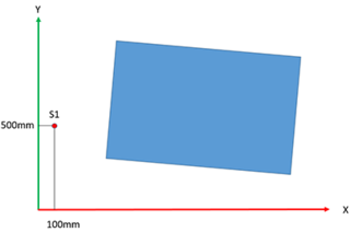
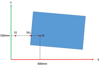
You can determine the 3 points to be entered, for example, by moving the TCP (e.g. with a measuring tip) to the 3 points in jog mode or automatically using TouchProbeMeasure. The Interface_MyRobot.Basic.OUT.SetpointPose.alrBase output variable or the Interface_MyRobot.PrgVar.astPoseValues[n] SRL variable parameterized for the measured Touchprobe position can be applied directly to the Position_1/2/3 input of the CoordSysMeasurement function block.
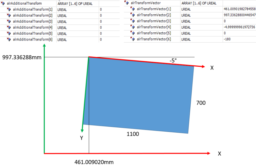
The transformation is calculated when the CoordSysMeasurement.ComputeTransform method is called, and output in the alrTransformVector as well as alrTransformFrame output variables if executed without errors.
The 3 points to be entered must lie in the XY plane of the coordinate system to be measured. The coordinate system to be measured can be tilted or rotated as required in relation to the reference coordinate system.
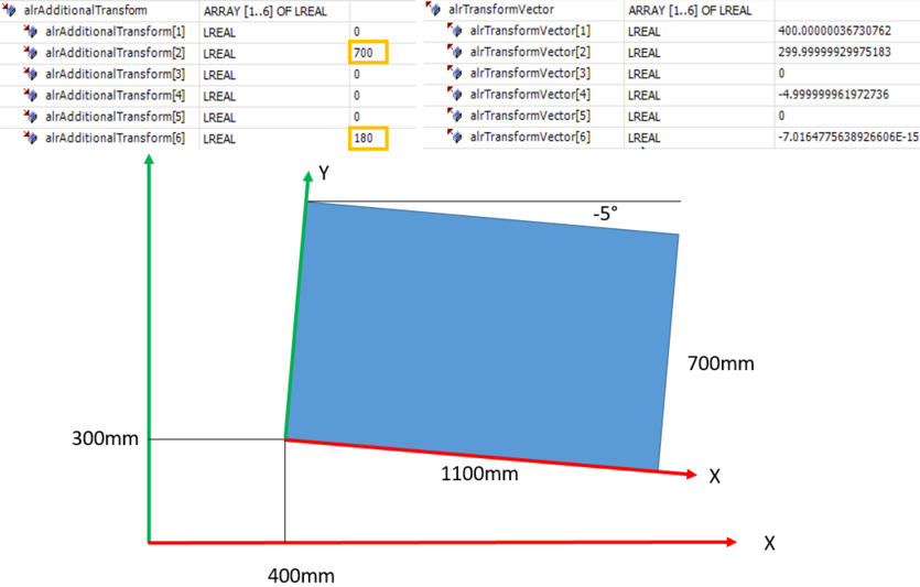
If the 3 points to be entered cannot be reached in the XY plane of the coordinate system to be measured, for example because the robot cannot move in the Y direction, then first rotate the coordinate system to be measured virtually, i.e. conceptually for the purpose of measurement, so that the 3 points become reachable in the XY plane. This means that you position the X‑ and Y‑coordinate axes of the coordinate system to be measured in the plane in which the robot can move. Additionally, enter the required rotation in the input variable alrAdditionalTransform in order to transform from the virtually placed coordinate system to the desired coordinate system, which is then output in the variable alrTransformVector after the method ComputeTransform has been executed.
To be able to reset an error of the function block via the robot, link it with the robot as follows, for example in the action User_PRG.Init:
xInitDone := (* xInitDone AND *)
fbCoordSysMeasurement.LinkISuperordinatedFB(SEW_GVL_Internal.MyRobot);