Example with electronics cover size 1
The following figure shows the connection of the equipotential bonding and the PE conductor:
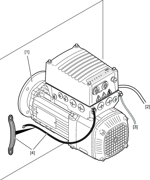
[1] | The mechanical installation of a drive unit with hollow shaft does not create a conductive connection of drive unit and mounting plate. In this case, a low-impedance, Hf-capable equipotential bonding [4] is required. The mechanical installation of a drive unit without hollow shaft creates a conductive connection of drive unit and mounting plate. In this case, the entire contact surface must be electrically conductive (e.g. unpainted). |
[2] | PE conductor in the supply system cable |
[3] | 2nd PE conductor via separate terminals |
[4] | EMC-compliant equipotential bonding, e.g., via ground strap (high frequency litz wire) The contact surfaces must be electrically conductive (e.g. unpainted). For improved low-impedance grounding at high frequencies, SEW‑EURODRIVE recommends using corrosion-resistant connecting elements. The HF grounding can be combined with the LF grounding on the terminal box. |
- Do not use the cable shield from signal cables for equipotential bonding.
INFORMATION