Belly sway
- Configure the mechanical parameters of the application in the "Basic settings" section. The following diagram shows the parameters available for this application type. For detailed descriptions of the parameters, refer to chapter Anti-sway control. The "Distance between lifting and traveling trolley" is calculated through "Height of the tower" / 2 because the belly sway is greatest at this height. The value is used for the parameter determination of "Spring stiffness between tower and traveling trolley" and "Damping ratio between tower and traveling trolley". If you do not already know the "Spring stiffness between tower and traveling trolley" and the "Damping ratio between tower and traveling trolley", e.g. from mechanical simulations, you can activate Support for parameter determination here.
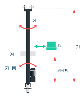
[1] | Height of the tower |
[4] | Mass of the lifting trolley |
[5] | Mass of the payload |
[6] | Mass of the tower |
[7] | Spring stiffness between tower and traveling trolley INFORMATION: To determine this parameter, see chapter Determining stiffness. |
[8] | Damping ratio between tower and traveling trolley INFORMATION: To determine this parameter, see chapter Determining stiffness. |
[9]+[10] | Effective lifting height |
- Define the effective lifting height by configuring the "Configured lifting height/offset" and the "Lifting height from fieldbus in mm" in the "Configuration of effective lifting height" section. The effective lifting height is calculated from the sum of these 2 parameters and describes the distance between lifting and traveling trolley on the basis of which the sway suppression is to be performed.
- Configured lifting height/offset: Fixed lifting height or an offset in [m]. This is often the lifting height with the strongest sway and thus equal to half the tower height.
- Lifting height of the fieldbus in mm: A value in mm can be specified via the fieldbus interface using the process data word "Distance between lifting and traveling trolley". Things such as variable lifting heights from external axes, for example, can thereby be taken into account.
- Specify the time window by configuring "Sway suppression" in the "Time window" section. The larger the time window, the more time is provided for the correction movement of the sway suppression and the dynamics of the correction signal is reduced. The positioning process is therefore extended by the time window. However, the jerk time of the travel axis can be reduced at the same time. A value is suggested for the parameter that you can adopt and adjust if necessary. The "Cycle time of the HighPrio task for limit value calculation" is also shown in this section. The displayed value is taken from the "Setpoint cycle control" parameter of the lower-level member.
