Size 8
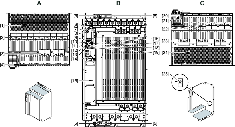
A | View from top |
[1] | X5: 24 V supply voltage |
[2] | X1: Supply system connection and +UZ, -UZ: DC link connection before DC link choke |
[3] | +UZ*, -UZ* (V DC link): DC link connection after DC link choke |
[4] | X6: Connection for Safe Torque Off (STO) |
|
|
B | View from front |
[5] | 4 × housing PE connection |
[6] | X33: Interface for CDM11A or CBG01A |
[7] | Product label with QR code |
[8] | S1/S2: EtherCAT® ID switch |
[9] | Status LEDs |
[10] | Memory module |
[11] | X23: Analog inputs or analog outputs |
[12] | X20: Digital inputs or digital outputs |
[13] | X22: Isolated relay contact |
[14] | Signal and control cable shield plate |
[15] | MOVILINK® DDI shield plate |
[16] | X60: safe digital inputs or digital outputs |
[17] | S4: Changeover analog input mA/V |
[18] | X30/X41 OUT: Fieldbus |
[19] | X30/X40 IN: Fieldbus |
|
|
C | View from below |
[20] | X18: FS encoder connection |
[21] | X16: MOVILINK® DDI connection |
[22] | Braking resistor connection |
[23] | X2: Motor connection |
[24] | X10: Brake control and motor temperature monitoring |
[25] | EMC contact screw on the right side of the inverter |
