Configuration
For the following application example, a MOVI-C® CONTROLLER is required as hardware. The real axes used are simulated.
Perform the following steps to configure the combi telescope:
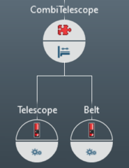
- In MOVISUITE®, in "Planning" mode, create a project with a MOVI-C® CONTROLLER (in the example: "UHX25A"), a software node ("CombiTelescope") and two axes ("Telescope", "Belt"). Place the telescope axis ("Telescope") on the left and the belt axis ("Belt") on the right below the software node.
|

- Configure a valid drive train for the two axes.
- Configure the user unit for the "telescope" and "belt" axes (the number of decimal places does not have to be configured here because this is done automatically by assigning the MOVIKIT® Gearing software module in the next step):
- User unit: User-defined unit: mm
- 1 revolution = 100 mm
- Position: mm
- Speed: mm/s
- Acceleration: mm/s²
- Assign the following software modules to the software node or axes:
- "Telescope": MOVIKIT® Gearing
- "Belt": MOVIKIT® Gearing
- "CombiTelescope": MOVIKIT® CombiTelescope
|
- Configure the software modules of the "telescope" and the "belt" axes:
- "Module configuration" > "Basic settings" – Activate simulation
- Configure the software module of the "CombiTelescope" software node:
- "Module configuration" > "CombiTelescope" – Number of belts: 1
- "Module configuration" > "CombiTelescope" – Length of belt conveyor: 800 mm
- "Module configuration" > "Fieldbus interface" – Belt stop distance via PD: FALSE
- "Module configuration" > "Fieldbus interface" – Belt pretravel distance via PD: FALSE
- "Module configuration" > "Fieldbus interface" – Belt overtravel distance via PD: FALSE
- "Module configuration" > "CombiTelescope" – Distance of box to belt end [3]: 60 mm
- "Module configuration" > "CombiTelescope" – Distance of telescope in home position to belt end [4]: 20 mm
- "Module configuration" > "CombiTelescope" – Belt stop distance: 50 mm
- "Module configuration" > "CombiTelescope" – Belt pretravel distance: 50 mm
- "Module configuration" > "CombiTelescope" – Belt overtravel distance: 70 mm
- "Module configuration" > "Fieldbus interface" – Activate fieldbus connection: Yes
- "Module configuration" > "Fieldbus interface" – Start address: 1
- The configuration results in the following process data assignment:
|

- Switch to "Startup" mode.
- Connect the MOVI-C® CONTROLLER in the project view with the MOVI-C® CONTROLLER in the network view and then update the IEC project.
