Assignment
The following table shows the terminal assignment of MOVIMOT® flexible DAC:
Terminal | No. | Marking | Function | |
|---|---|---|---|---|
X1 | 1 | Brown | L1 | Line connection, phase L1 – IN |
2 | Black | L2 | Line connection, phase L2 – IN | |
3 | Gray | L3 | Line connection, phase L3 – IN | |
11 | Brown | L1 | Line connection, phase L1 – OUT | |
12 | Black | L2 | Line connection, phase L2 – OUT | |
13 | Gray | L3 | Line connection, phase L3 – OUT | |
| – | – | PE | Protective earth connection |
X3 | 1 | – | BW | Braking resistor connection |
2 | – | BW | Braking resistor connection | |
X9 | 1 | Yellow | F_STO_P1 | Input STO+ |
2 | Yellow | F_STO_P1 | Input STO+ (to loop through) | |
3 | – | 0V24_OUT | 0V24 reference potential | |
4 | – | 24V_OUT | DC 24 V output | |
5 | – | DI01 | Digital input DI01 | |
6 | – | DI02 | Digital input DI02 | |
11 | Yellow | F_STO_M | Input STO_ground | |
12 | Yellow | F_STO_M | Input STO_ground | |
13 | – | 24V_IN | DC 24 V supply | |
14 | – | DOR-C | Relay output DO R, common contact | |
15 |
| DI03 | Digital input DI03 | |
16 |
| DI04 | Digital input DI04 | |
21 | Yellow | F_STO_P2 | Input STO+ | |
22 | Yellow | F_STO_P2 | Input STO+ (to loop through) | |
23 | – | 0V24_IN | 0V24 reference potential | |
24 | – | DOR-NO | Relay output DO R, NO contact | |
25 |
| 0V24_OUT | 0V24 reference potential | |
26 |
| 24V_OUT | DC 24 V output | |
X31 | 1 | – | 0V24_OUT | 0V24 reference potential |
2 | – | CAN_L | CAN Low connection | |
3 | – | CAN_H | CAN High connection | |
4 | – | 24V_OUT | DC 24 V auxiliary output | |
X16 | 1 | – | DDI | MOVILINK® DDI |
2 | – | DDI_GND | MOVILINK® DDI reference potential | |
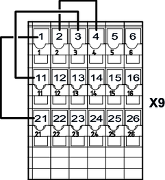
The following figure shows the factory-installed jumpers at the X9 terminals:

These jumpers are not present in the following designs:
- Designs with plug connectors with STO function
For further information, refer to the product manual > chapter Project planning for functional safety and chapter Connection variants for functional safety.


