Energy storage system (EnergyStorageSystem)
The in-house SEW energy storage cabinet ESS Rx communicates with the MOVI-C® CONTROLLER via an EtherCAT®/SBusPLUS bus coupler with digital and analog inputs and outputs.
To make reading out the inputs and outputs as convenient as possible, the SEW_PES_EnergyStorageSystem library contains communication function blocks for the energy storage cabinet.
The library contains the following function blocks (depending on the number of installed energy storage modules):
- IOConnector_ESS_Rx_6Modules
- IOConnector_ESS_Rx_7Modules
- IOConnector_ESS_Rx_8Modules
- IOConnector_ESS_Rx_12Modules
- IOConnector_ESS_Rx_14Modules
- IOConnector_ESS_Rx_16Modules
Each of the function blocks has the following structures with input variables and the associated variables for mapping the inputs to inputs and outputs of the associated terminals of the bus coupler:
- EnergyStorageSynchronization – contains all DI/DO variables for controlling the contactors for switching the energy storage unit on and off.
- MRCD – contains DI/DO variables for controlling the modular RCDs.
- MultipleFuseControl – contains DI/DO variables for controlling the multi-fuse concept.
- EnergyStorageModuleDiagnosis – contains an array with 6 to 16 diagnostic function blocks (depending on the selected function block) for connecting the diagnostic interface of LSMTRON energy storage modules.
INFORMATION

The temperature values must be in the format created by the OAI45C analog input on the OCE1n bus coupler (an INT with a decimal place, for example 231 = 23,1 °C).
Proceed as follows to connect the energy storage unit using this function block. In this example, an ESS Rx with 8 energy storage modules with an OCE11 bus coupler is used.
- Instantiate, for example, a local instance of the IOConnector_ESS_Rx_8Modules in the User_PRG of the USER_Application :
_fbIOConnectorESS: SEW_MK_PES_PowerMode.IOConnector_ESS_Rx_8Modules;- Add, for example, in the User_PRG.Init the following linking of the communication function block with the software module and the logical device. INFORMATION: MDP1 refers to the software module used and LogicalDevice_OCE11 refers to the LogicalDevice of the OCE11 bus coupler. If necessary, these must be adapted to the designation of the devices in your project.
_fbIOConnectorESS.LinkModules(itfMOVIKIT := MDP1, itfLogicalDeviceOCE1nC := LogicalDevice_OCE11);- Add the input and output variables of the function block one after the other to the corresponding variables of the EtherCAT® mapping of the OCE1n bus coupler.
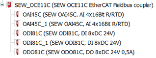
- For ESS Rx, the bus coupler with its terminals could have the following structure, for example:
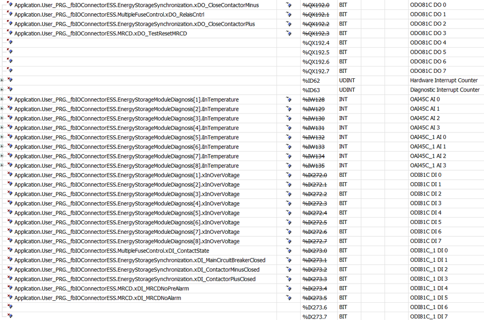
- With this structure, an example assignment of the terminals and variables would look as follows. Connect the corresponding variables for your ESS Rx, depending on the wiring diagram.
- The communication function block is completely connected. The functions of the software module now query the variables automatically. No further programming steps are required. The energy storage modules of the ESS energy storage cabinet are automatically assigned the stack ID 255 internally.
