Single-stage fuse concept
If only one circuit breaker is used for storage unit protection, a continuous current load that is too high for the fuse may occur when charging the energy storage unit. Overload during operation is prevented by the SEW design.
Selection example
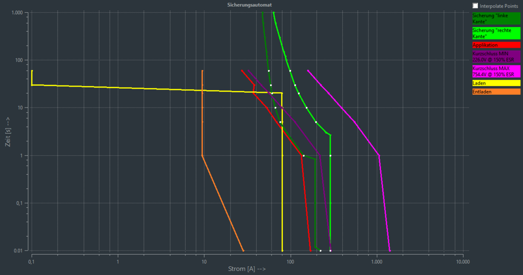
The figure shows the currents that occur over current and time of an example selection. The yellow line indicates the charging of 0 V. The two green lines indicate the switch-off range with tolerance band of the fuse. You can see that the charging process reaches in there. The single-stage fuse concept prevents this by limiting the charging current up to a selected voltage to 80% of the nominal fuse value. During operation, the fuse range is no longer reached as shown by the red line. The operating mode does not require the connection of the additional relay.
