Configuration
- A MOVI-C® CONTROLLER, a real axis, and a switch are required as the hardware for the following application example.
- The switch is used to simulate touchprobe signals and must be connected to the touchprobe input (DI 04) of the inverter.
- In MOVISUITE® in "Planning" mode, create a project with a MOVI-C® CONTROLLER, one virtual axis ("master") and one real axis ("FlyingSaw"). In the application example, the virtual axis acts as the master axis.
- Configure a valid drive train without user units for the real axis.
- Assign the following software modules to the axes:
- Configure the user unit for the "master" axis:
- Configure the user unit for the "FlyingSaw" axis:
- Configure the software module of the "master" axis:
- Configure the software module of the "FlyingSaw" axis:
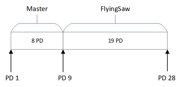
- The configuration results in the following process data assignment:
- Open the configuration of the MOVIRUN® flexible.
- Select a fieldbus protocol in the "Fieldbus" configuration menu in the "Fieldbus card" section.
- Switch to "Startup" mode.
- Connect the MOVI-C® CONTROLLER in the project view with the MOVI-C® CONTROLLER in the network view and then update the IEC project.