Switching time for the output
A minimum switching time can be specified for the output in each cam window. If the time for passing through the cam window is greater than the minimum switching time, the output is not switched off after the switching time has elapsed.
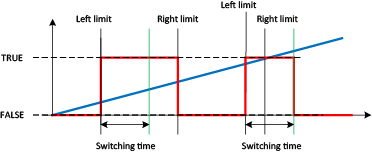
The following diagram illustrates this switching time. The source signal is shown as a blue line and the switching level as a red line.
A time cam is used when the left limit is set equal to the right limit and a switching time greater than 0 is configured. In this case the output is activated for the set switching time when the limit is reached.
